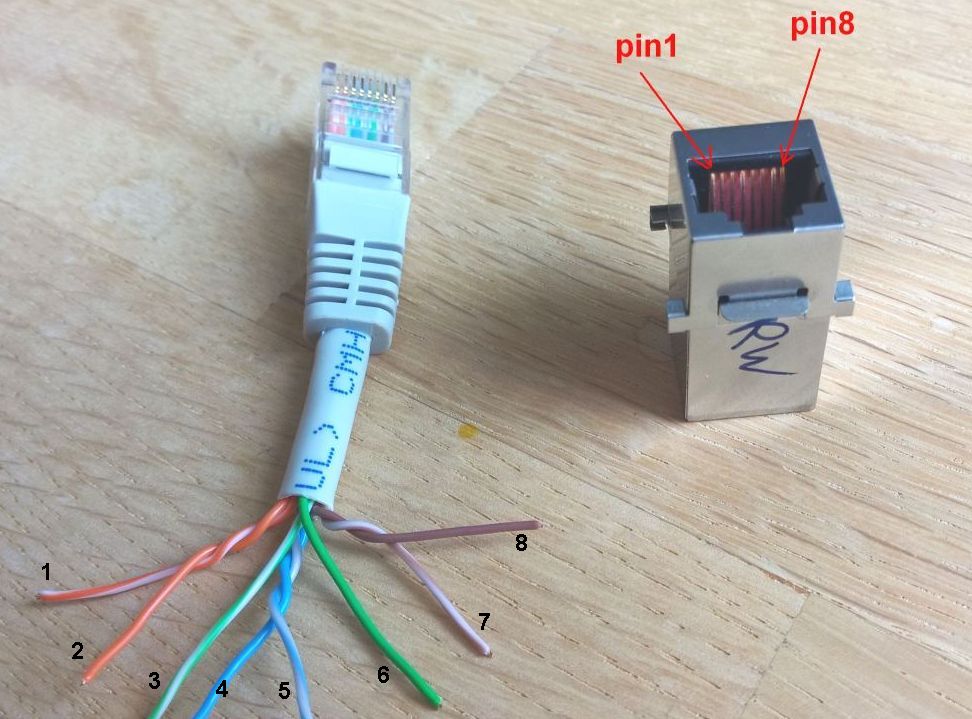
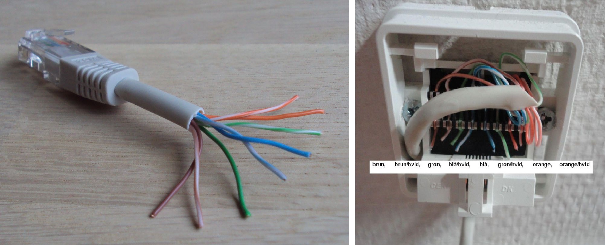
LAN connector (RJ45) pin numbers and wire colors:


PoE:
PoE means Power Over Ethernet, and means that it is possible to use part of the LAN cable for powersupply routing.
Here are the standard connections:
standard T568B: (normal cables)
pin color  name10/100  name1000
1   or/wt  RX+     pair2  A+
2   or     RX-     pair2  A+
3   grn/wt TX+     pair3  B+
4   blu    DCpos   pair1  C+
5   blu/wt DCpos   pair1  C+
6   grn    TX-     pair3  B+
7   brn/wt DCneg   pair4  D+
8   brn    DCneg   pair4  D+
standard T568A: (as other end of a crossover cable)
pin color  name10/100
1   grn/wt TX+
2   grn    TX-
3   or/wt  RX+
4   blu    DCpos
5   blu/wt DCpos
6   or     RX-
7   brn/wt DCneg
8   brn    DCneg
Both the above configs are mode B, where DC and Data is separated.
This uses pins 4,5 for one side of DC, and pins 7,8 for the other side.
Alternative is mode A, where DC and data share the same wires:
This uses pins 1,2 for one side of DC and data, and pins 3,6 for the other side.
pin numbering
Looking into a socket (jack) with the lock-hole downwards, you count 1 to 8 from left to right.
You could also do that from the cable side of a plug with the lock downwards, pins upward.
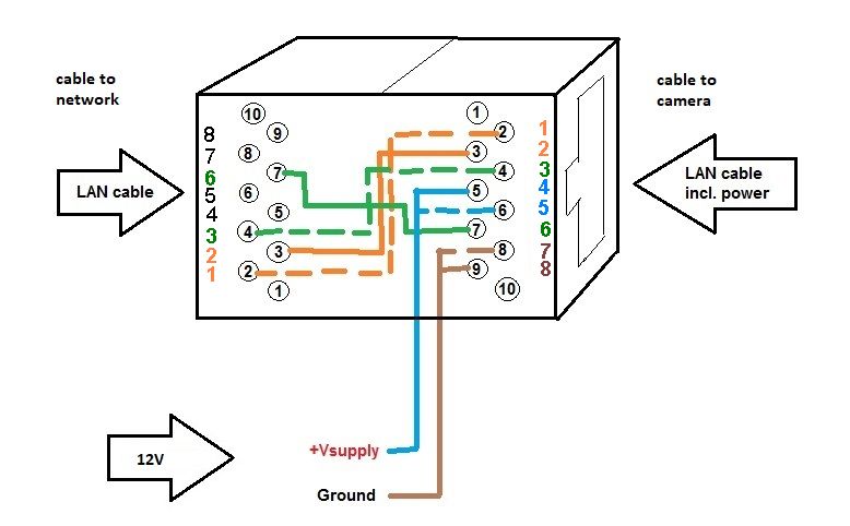
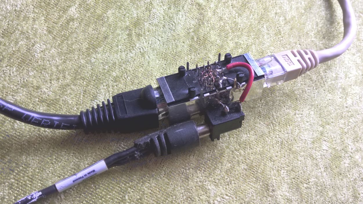
You can make your own PoE injector, by soldering two female RJ45 connectors back to back, and wiring them like this:
(picture shown for two 10pin connectors, where only the middle 8 pins are used)

Specifications:
-IEEE 802.3af and IEEE 802.3at (POE Plus).
-Voltage 24V AC/DC up to 60V AC/DC (normal is 48V DC)
Links :
some homemade descriptionNB unsure here what is tx and rx and dc + or -.
good and cheap PoE set from TP-link, with 48V supply and built-in 5/9/12V smps at output side