can it be hacked?
This is a Xyloband design, with a big RGB LED in the middle and several smaller LEDs in the band itself.
It can be remote controlled by a radio transmitter.
We don't have access to a transmitter, which would have made it easy to reverse-engineer the signal.
But the electronics are much simpler than the previous versions of the Xylobands, so there is a change that we can find out...
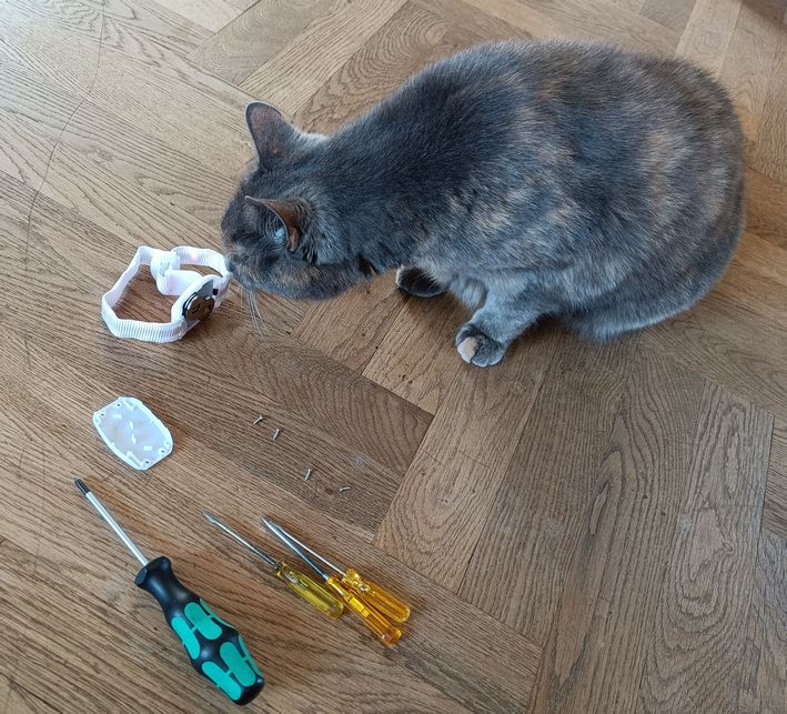
What is inside:
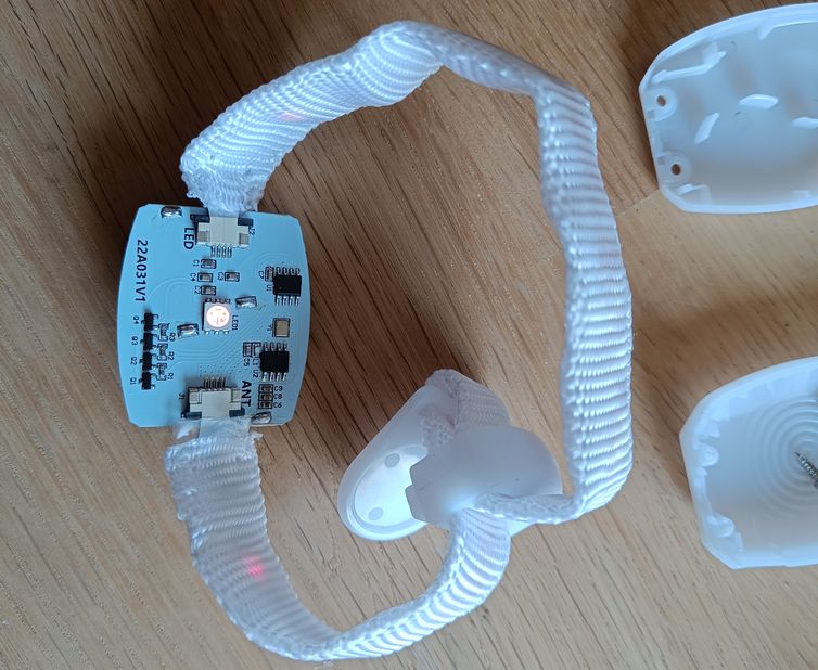
When opening the encapsulation, we see 2 battery supplies,
A single CR20323 (the 3V supply to the chips) and 2x CR2025 (the 6V supply to the LEDs).
The 6V supply will probably be drained to below 3V already, as the LEDs were left ON after the Eurovision event.
On the other side of the board, we see the electronics.
The board has 2 connectors, where one has the connections to the LED strip in the band, the other just connects to a strip in the band that functions as an antenna.
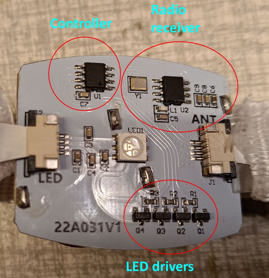
The circuit itself consists of a Radio receiver, a Controller, and RGB (red/green/blue) LED drivers.
The radio chip U2 is a CMT2210LC with a 27.1383MHz crystal Y1. The receiver works on a frequency of 433.92MHz, which is 16 times the crystal frequency.
It is a non-programmable circuit with a logarithmic signal chain that receives and detects OOK (on/off keying) signals.
It has a Data output pin4 and a PowerDown input pin3.
The controller chip U1 is unknown, but it is either a very simple Microprocessor or an FPGA.
It both decodes the Data output from the radio and controls the PowerDown timing, so it must have a built-in clock circuit.
The 4 driver transistors Q1-4 are controlled by 3 outputs from the controller via the resistors R1-3.
The capacitors C1-4 are RF decouplings of the LEDs in the band.
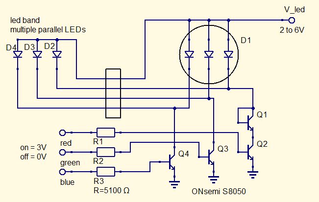
The LEDs in the band are wired in parallel with LEDs in the big LED in the middle of the board.
How are the LEDs connected:
As drivers, bipolar transistors are used instead of FETs. THis is less efficient, but probably cheaper, and it has the advantage that one of them can be used as diode in order to better balance the intensity at low V_led.
Another advantage is that LED current can be limited with a controlled base current.
The S8050 transistors have a Hfe of 250, thus with a basecurrent of 2.2V/5.1kOhm= 0.4mA they can sink approx 100mA total LED current.
Taking a quick look at the signals while only noise is received:
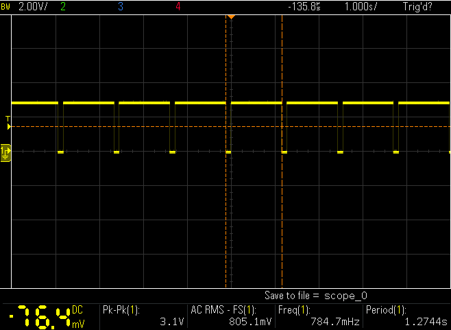
The signal on the U2 PowerDown pin shows that the Radio chip is powered up in 120ms during a repeating cycle of 1.275seconds.
This will reduce the average current that the chip uses to approx. 1/10.
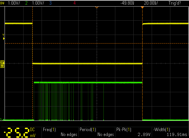
The data output has the same timing, see the following zoomed-in measurement.
In the plot below, channel 1 is PowerDown and channel 2 is Data (which here is noise).
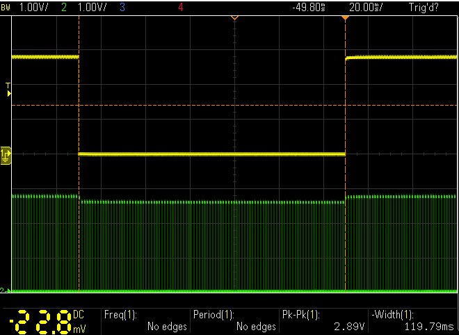
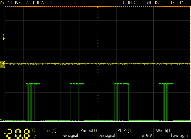
The Controller chip is not powered down, because it has to keep on controlling the LEDs even when the radio is not receiving any signal.
The following plots show the Controller output pin7 (channel2) together with the PowerDown pin2 (channel1).
The second plot is zoomed in, so the pulse-width-modulation (which determines the light intensity) can be seen.
Next steps are:
# Investigate how the LED colours be controlled with simple microswitches mounted on the board.
# Rig up a signal generator as transmitter, in order to see if it is easy to send a signal that the controller understands.
>>>>> TO BE CONTINUED SOON...
NB NB NB NB :
if you have some more info about the controller chip, pls write me a message at webmaster.obi1@gmail.com !!!!!
this page is made with n073p4d 2