Ever wondered what's inside a LED lightbulb and if it can be repaired when defective?. .
Here follows a description of how to take a defective LED lightbulb apart, find out what is inside and repair it.
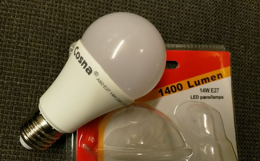
The following picture shows my favourite LED bulb, a Cosna 14W, 1400 Lumen, 2700k.
It was my favourite because of the amazing amount of emitted light.
But the thing suddenly (dec2019) stopped working alltogether after less than 2 years of use, which in this case not even accumulated to 1000 hours.
Fortunately, the bulb was easy to disassemble and reverse-engineer.
So here is the result of my findings.
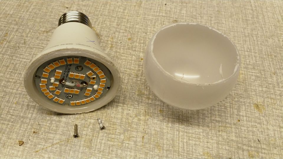
Here the plastic cap was sawn off.
By the way, as I found later, the cap was just glued onto the body and could have been removed with a knife and some patience.
When examined closely, some of the LEDs are black on the inside and obviously burned out.
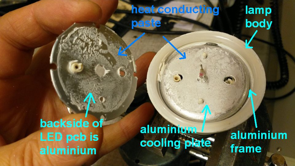
Next step was to remove the LED pcb (printed circuit board) after removing 2 screws and desoldering 2 wires.
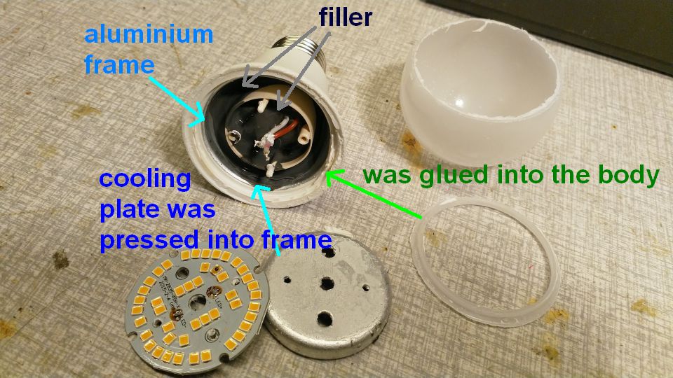
Here we see that there is decent cooling with an aluminium plate pressed into an aluminium frame (frame covers the inside of the plastic body).
Under the plate we can locate the SMPS (Switch Mode Power Supply) circuit covered with grey rubberish filler.
The fill is probably conducting the heat from the SMPS circuit to the frame.
The SMPS powersupply is needed to convert 230V AC voltage to a DC output current driving the LEDs.
Checking the LED board:
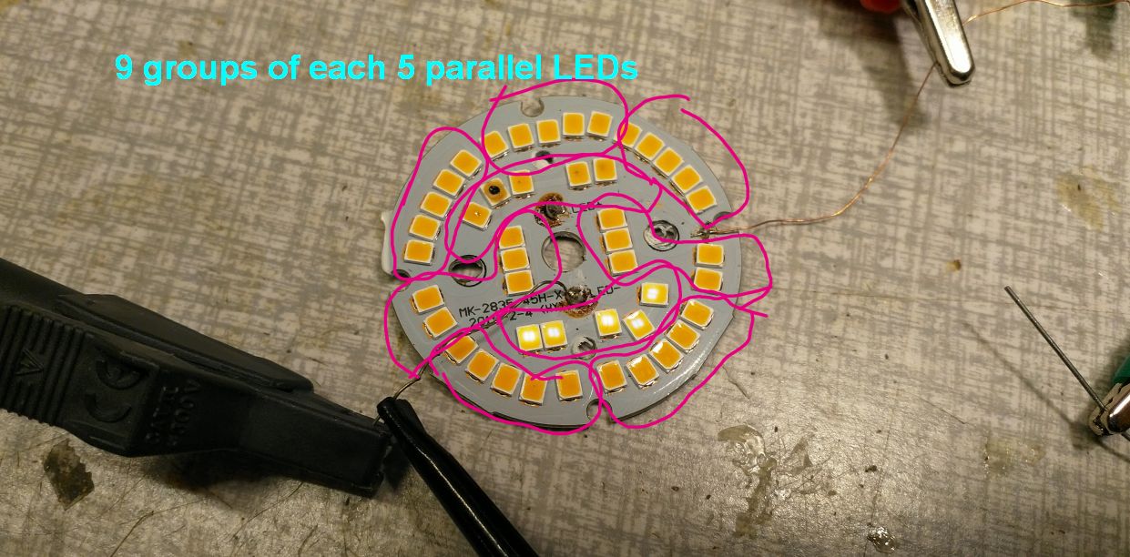
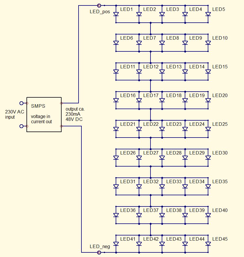
The LEDs are arranged with 5 in parallel, and 9 of those groups in series.
Connecting each of those groups individually to a supply with a series resistor of 1kOhms, showed that all of LEDs in the "burned-out" group were an open circuit, and that all others groups lighted up fine.
The voltage that was needed to light up, was slightly more than 5V. This means that each led probably internally has 2 chips in series (what also can be observed optically when they are supplied with a very small current).
I_LED V_LED
3mA 5.08V
5mA 5.12V
10mA 5.16V
25mA 5.26V
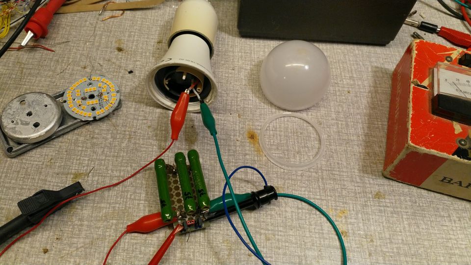
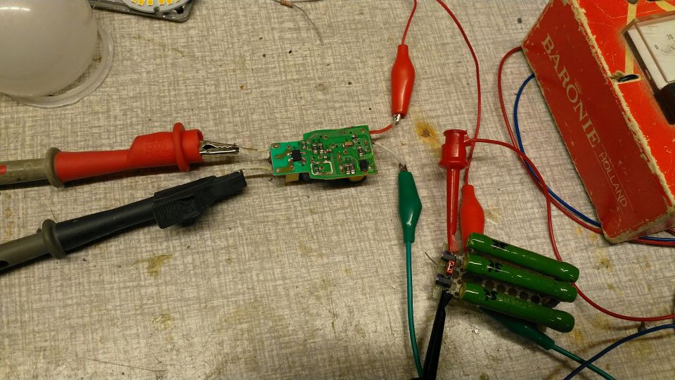
In order to determine the operating current of the LEDs and generally to check if the bulb's currentsource SMPS (Switched Mode Power Supply) was still working, the bulb body was connected to 230V and the output loaded with a power resistor.
Nothing exploded..
As the output voltage into LEDs is nearly constant over current, a good guess for a situation with all working LEDs is 9 x 5.3 = 48V.
Power is 14W according to the supplier, so the equivalent load resistance was guessed with P=V^2/R; 14W = 48^2 / R => R = 165 Ohms.
The output was measured with different resistor values:
R Vload Iload
150 35V 230mA
200 48V 240mA
NB with 150Ohm, it would not start up every time while resistor was connected.
Conclusion : the SMPS still works, and the delivered power in 48V is 48V^2/200Ohm= 11.5W.
So if we just shorted the burned-out group of LEDs (LED 1 to 5 in the following schematic) and mounted the stuff again, the bulb could probably still work and deliver 230mA into 8x5.3= 42V which gives 42Vx230mA = 10W.
But of course it is more fun to discover how the thing is working, so instead of doing the easy repair it was chosen to continue the tear-down.
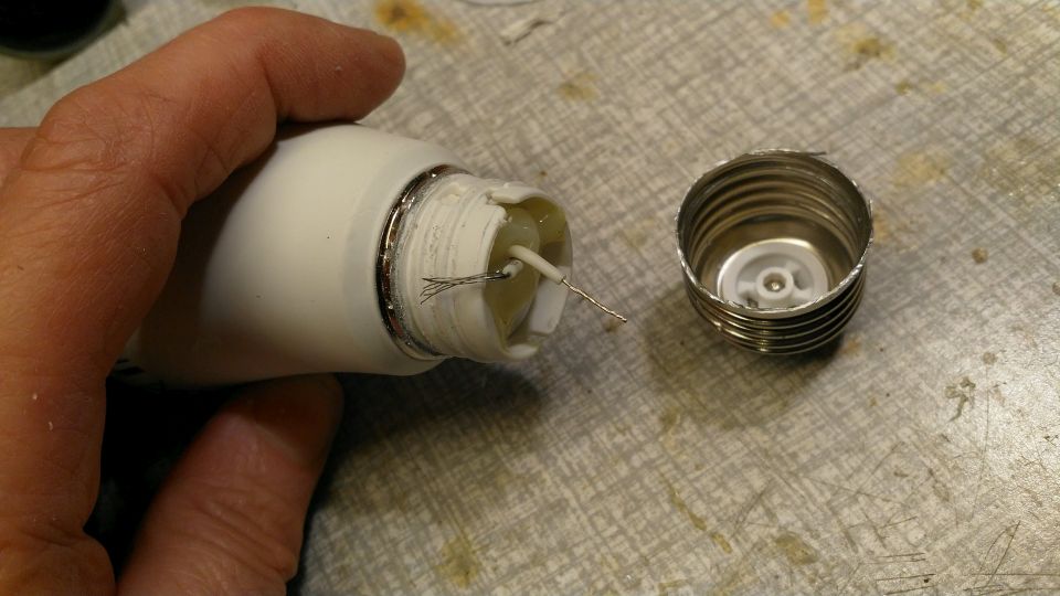
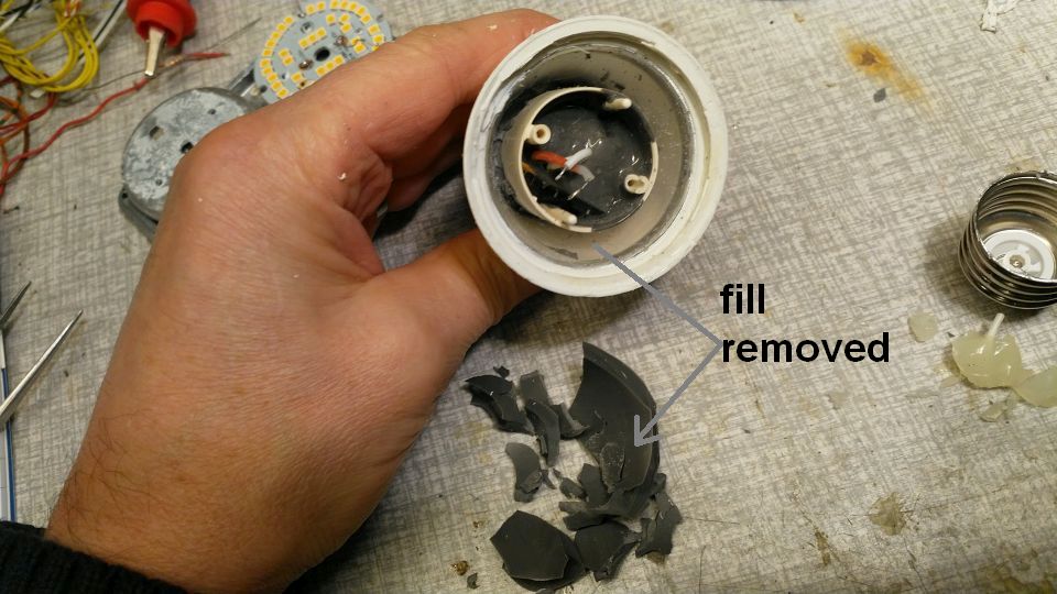
After the outer fill was removed, the inner part could be pushed out:
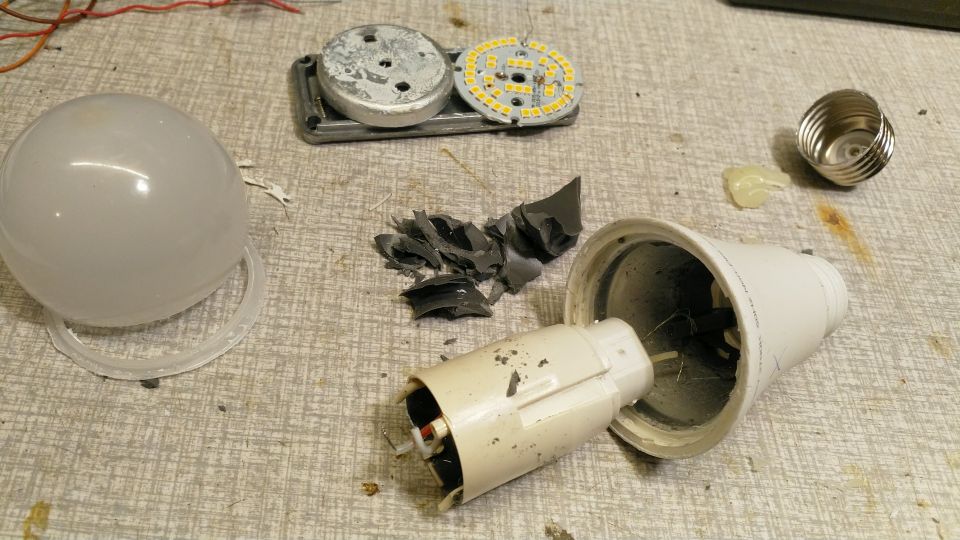
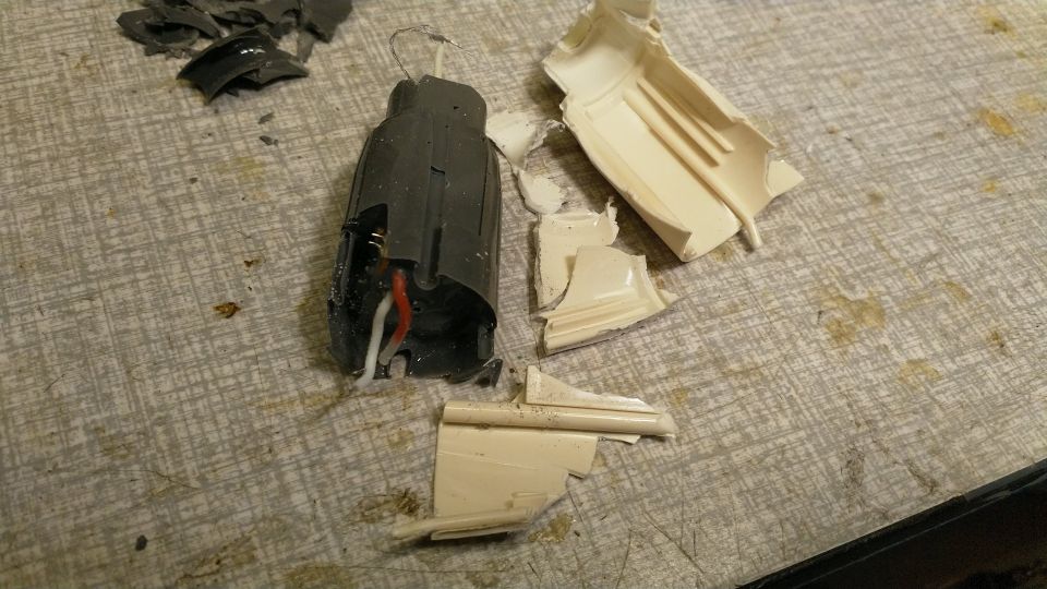
The inside fill could be carefully removed, revealing the SMPS board:
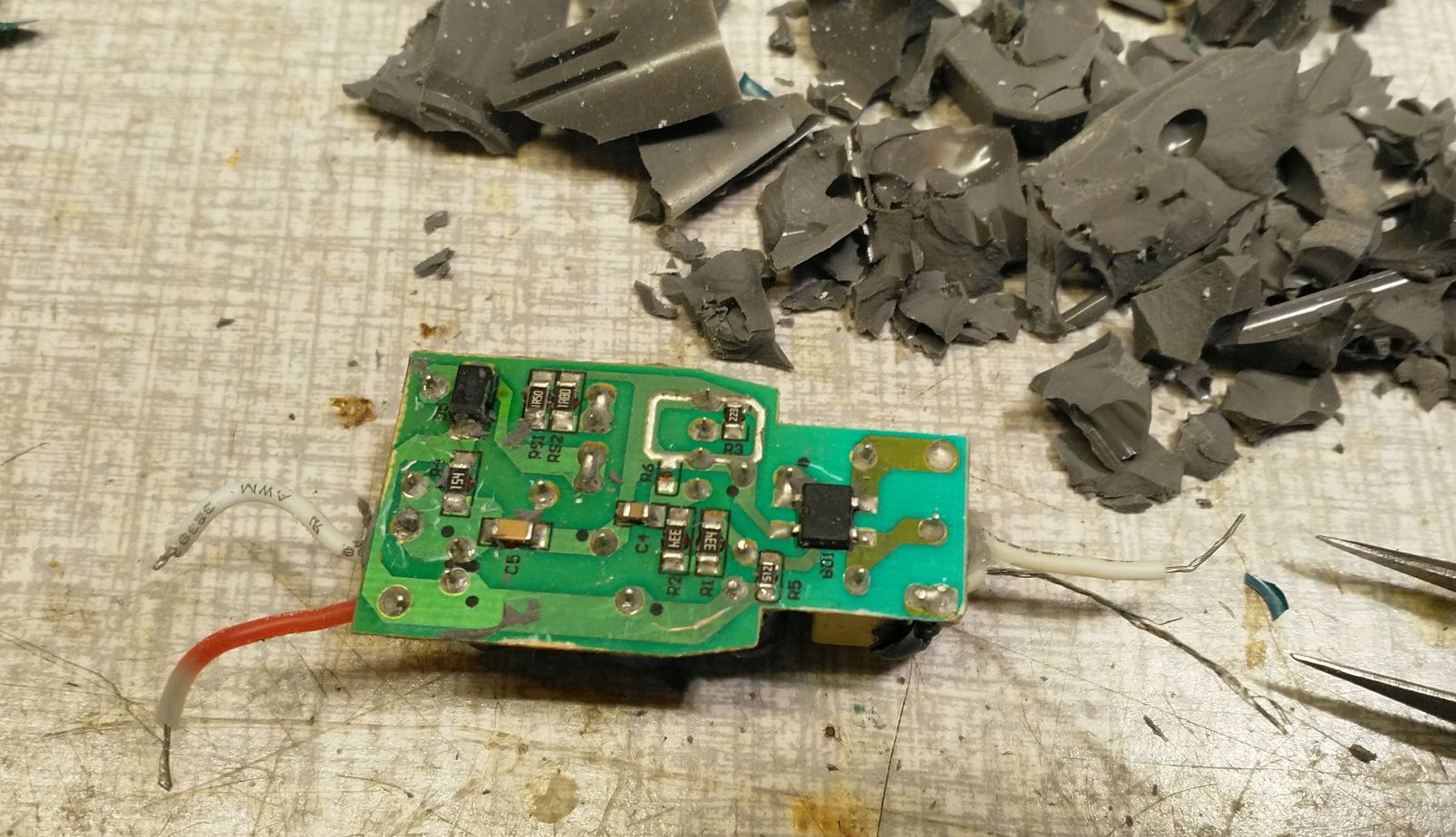
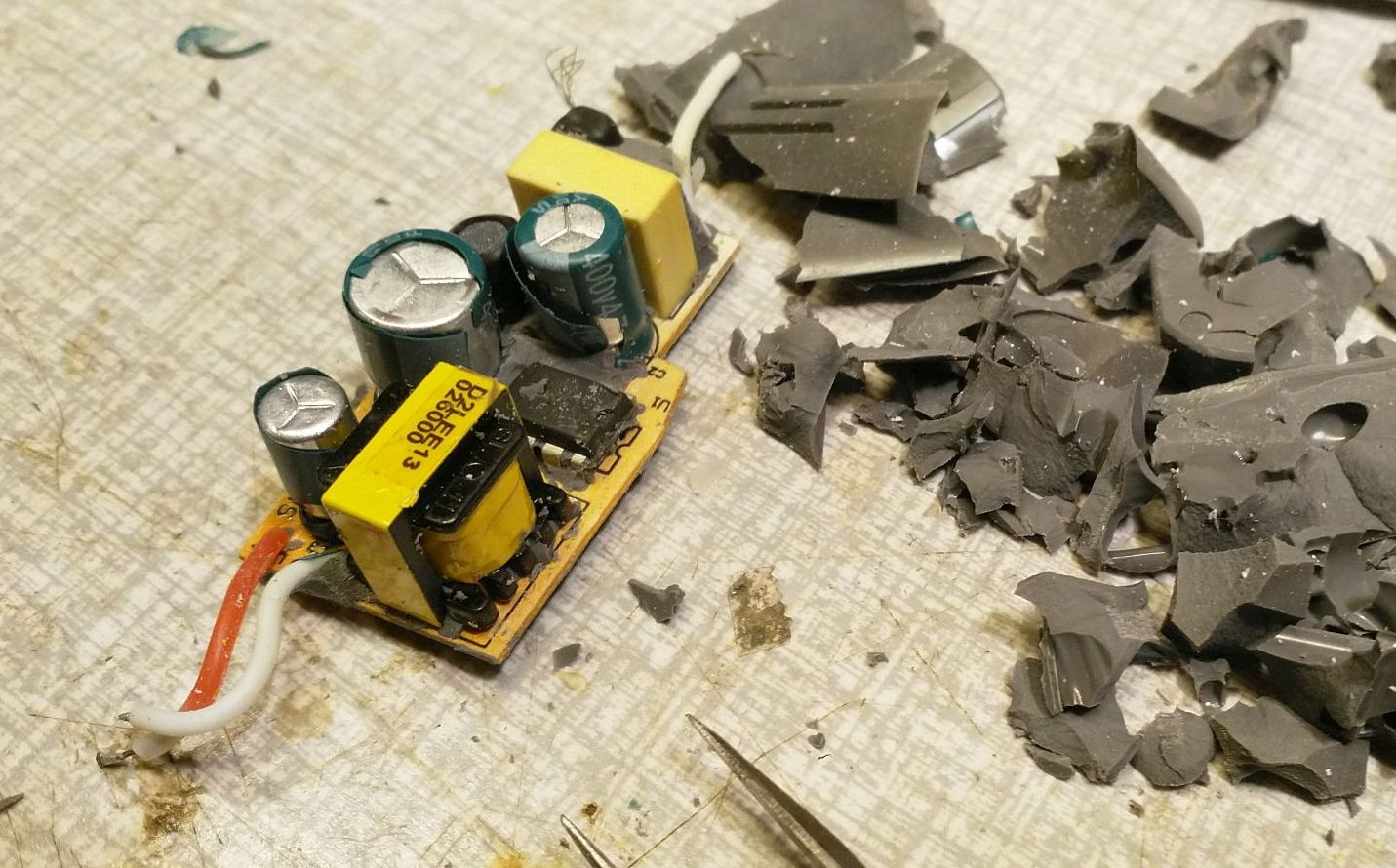
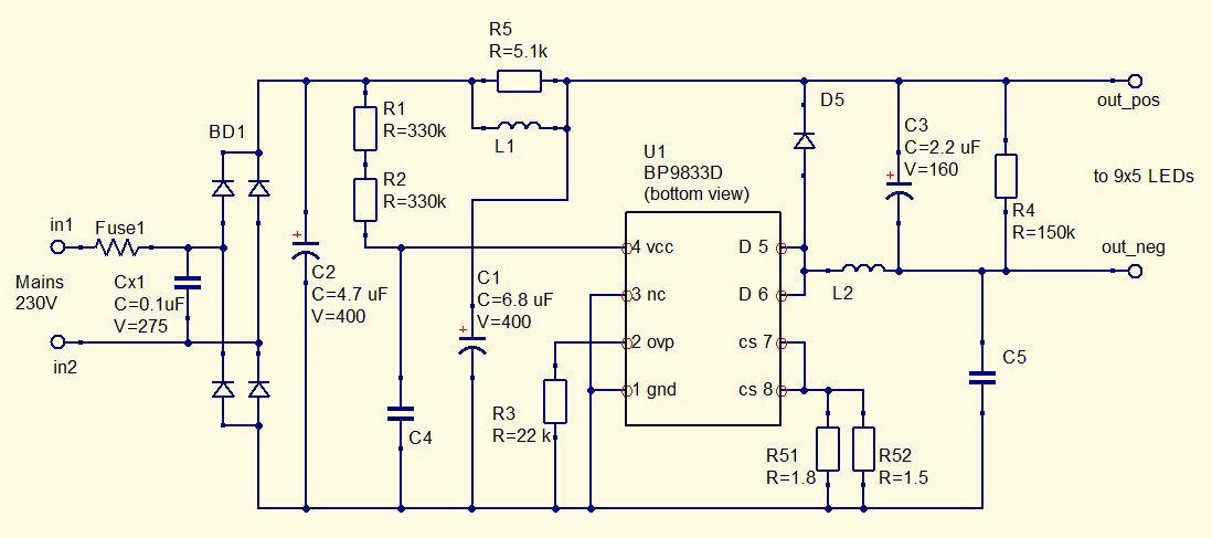
Drawing the schematic was quite straightforward, because the board has only copper traces on the bottom side.
It is a buck smps with minimal EMC filtering (Cx1, L1, C5).
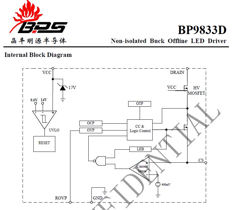
click the picture to download the datasheet
Description of more measurements and use of the parts will follow later:
this page is made with n073p4d 2