This is a description of how to modify a cheap Jydsk christmas led chain, so the light intensity is controlled by your music or other sound, using a built-in microphone.
Everything fits easily inside the orignal battery box.. .
This christmas lightchain, bought at JYSK for DKr11.75 is an outdoor led chain, with a button that switches ON / Timer / OFF.

The text on the backside is a bit misleading, as I measured the LEDs to draw only 40mA total..

The battery compartment can house 3 AA batteries. that is a really good thing compared to so many other light-chains; AA has much more capacity than AAA, and 3 instead of 2 cells gives us much more possibilities for making the electronics.
The LEDs in the chain are all in parallel.

The top compartment houses a little circuit board with a "switching circuit". The chip switches the negative rail On and Off.
The LED string is connected through a 39R series resistor (R1) which sets the current.

The modification is as follows;
Basically, the 39R series resistor is removed, and replaced with a little circuit that controls the current through the LEDs.
Depending on how loud the sound is, the LEDs will light up more or less (off without sound).
The schematic (drawn with QucsStudio):

The circuit does the following:
The microphone in an electret type, that needs a voltage of approx. 2V at its output.
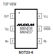
The microphone signal is amplified 120 times with the MAX4236 chip, which is a low-voltage Opamp.
The gain is set by R1/R2.
C2/R2 sets the low-frequency cutoff.
The positive input is biased with D1 to approx. 0.5V, which also is the Opamp output voltage when there is no microphone signal.
When the microphone hears a weak sound, there will be a signal with a voltage around the 0.5V bias, and for larger signals the voltage will be between 0 and 3V.
The transistor T1 will start to deliver a little current to the LEDs when the Opamp output voltage to R7 comes above 0.7V, and the LEDs will be at maximum light when that voltage is approx 2V.
The following oscilloscope pictures show the Opamp output voltage at R7 for a weak (tone) and a strong (music) microphone signal.


The modification was built on a standard "hole-board" like this:


The layout looks like this. The red traces and components are on the backside of the board:

The wires from P1,P2,P3 are connected like this, after removal of the original series resistor:

The microphone is taken from an old phone headset:


Here the microphone is mounted (use tacky wax).
NB You have to drill a 2mm hole in the lid of the box, just above the microphone, to let the sound in.

The opamp is so tiny, that you have to solder some wires to its pins in order to be able to mount it in the board.


MAX4236 datasheet (click to read pdf):
.
this page is made with n073p4d 2