Ever wondered why those motion sensors that switch on your entrance light, can run on 230V without some switchmode powersupply?
And can they be modified to run on 12V, when you need such sensor in a remote place?. .
Here follows a description of how the supply works, and most of all how to modify it for running on 12V and directly controlling a LED lamp.
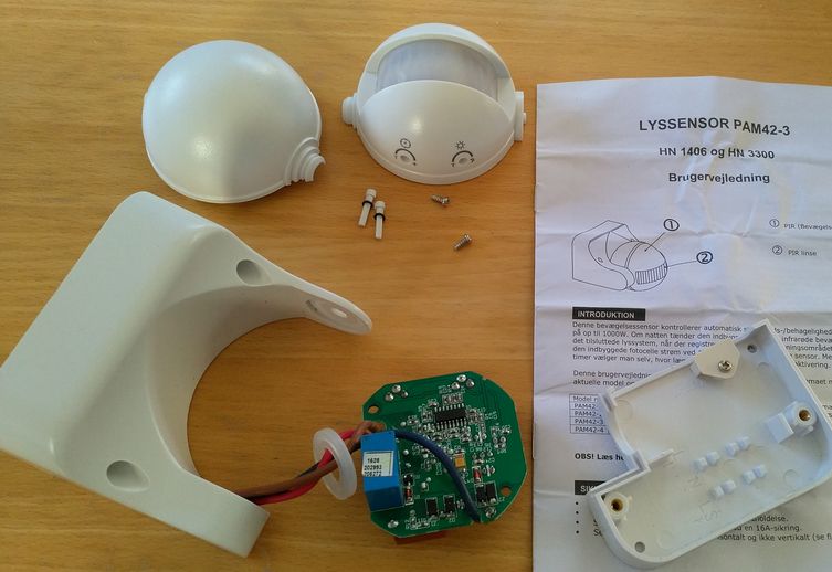
The following picture shows a 180degree PIR motion sensor PAM42-3.
The good thing about this one is, that it is watertight but still easy to disassemble. No glued parts.
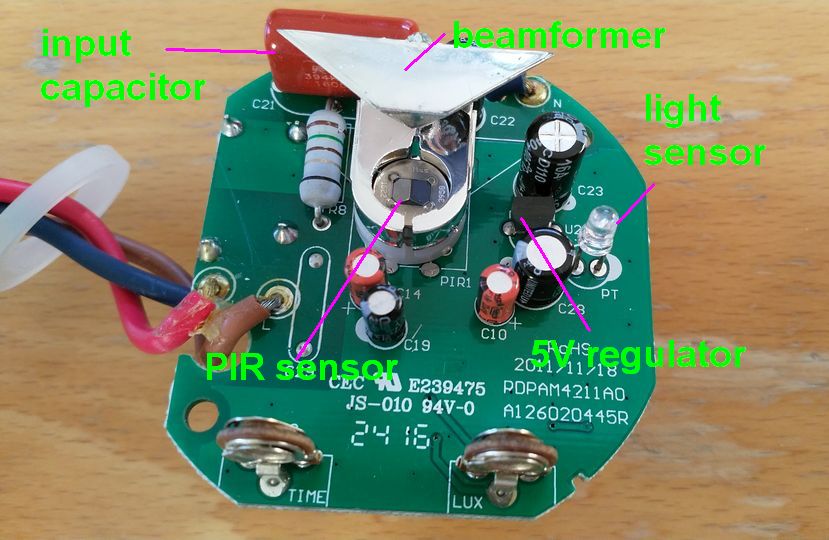
When examined closely, the following main components can be located on top and bottom of the board:
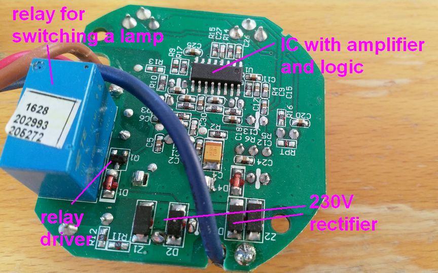
The IC obviously runs on 5V, but the relay is a 24V type.
The diagram can be drawn, in order to investigate the powersupply.
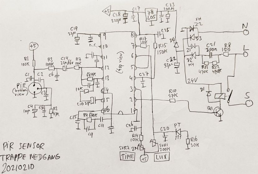
Here we learn that it has a series capacitor (C21) as a voltage divider.
That has the advantage that no power is lost in the voltage drop, as the voltage over a capacitor is 90degree out of phase with the current through it.
For example, when we measure voltage and current separately: 230V x 14.8mA= 3.4W. But when we measure with a Wattmeter that also uses the phase, it shows 0.6W.
The drawback is, that spikes and pulses on the 230V line go straight through the capacitor and will easily damage the electronics, so extra circuitry must be implemented for protection.
(Also, this trick is only usable for very low power, because for higher power there are regulations for a powerfactor >0.9 in order to guarantee the efficiency of the 230V mains distibution system. Powerfactor is cos(phi), where phi is the phase between voltage and current)
Checking the supply circuit for possibility of 12V modification:
The rectifier bridge has two normal diodes (D2, D3) and two spike-absorbing zenerdiodes (Z1, Z2) with 24V limiting voltage.
This clamps the voltage to 24V even when the drawn current varies (activating the relay uses much more current than during idle), and at the same time it forms (together with the series resistor R8) the protection against spikes and pulses on the 230V line.
This is a good solution, but it will inevitably introduce some extra current through the zenerdiodes during idle. (as we will see later, when we measure the current consumption of the modified 12V version).
The 24V is only needed for the relay.
The 5V regulator will work fine with 12V instead of 24V, so removing the voltage divider and replacing the relay is a good solution.
When we want the motionsensor to switch a LED light, it is easier and cheaper NOT to use a 12V relay but just use a good PowerFET instead. The drawback is, that it only can switch DC current and not AC, but as we had a DC powersupply for the lamps anyway, this is no problem.
(By the way, using an AC powersupply is also possible if an extra terminal is added for the + of the lamp, connected to the common cathode point of D2, D3. Then Z2 shall not be shorted, so we still have the bridge-rectifier in the circuit.)
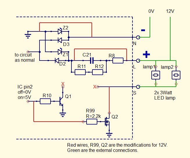
So, it is only needed to remove the relay, and to mount some wires and a FET.
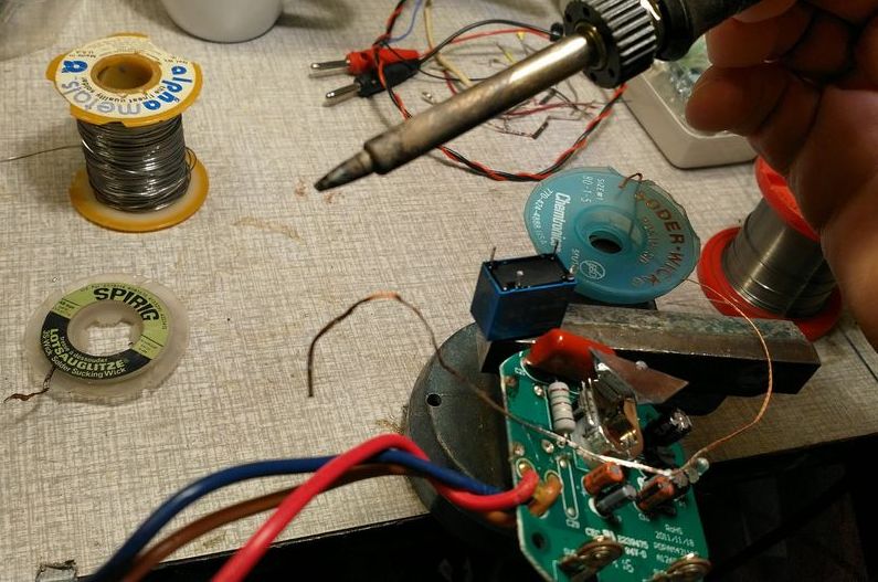
Use solder wick to suck up the tin in order to remove the relay:
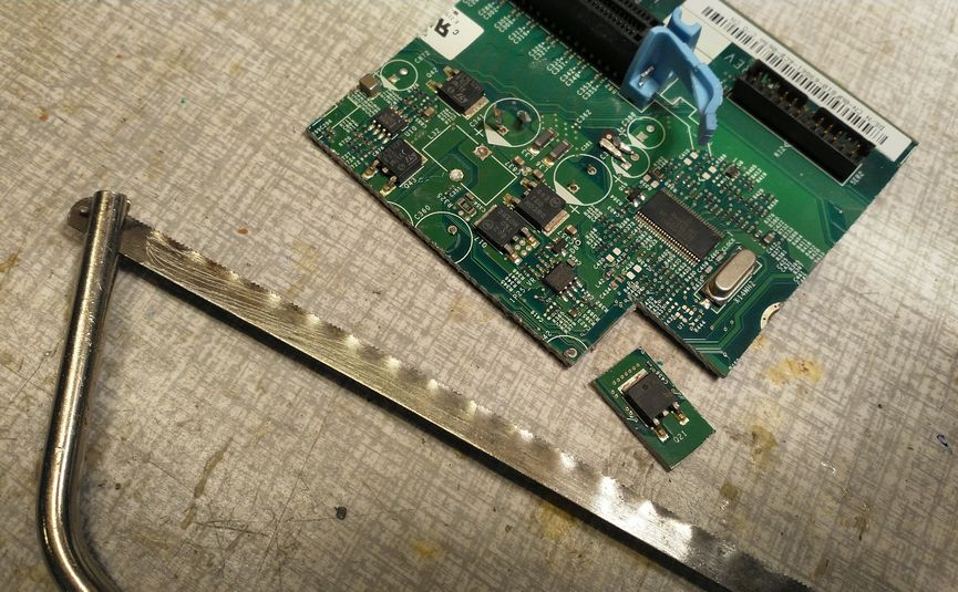
Good PowerFETs can be found in scrap electronics, e.g. old PC motherboards:
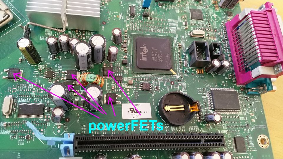
These FETs normally have a very low R_on resistance, typically 40mOhms, and can switch many Amps of lamp current.
But you should check the Gate voltage that is needed to switch the FET on.
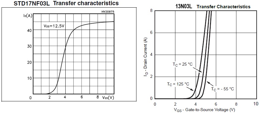
E.g. on the motherboard shown above, there were 2 similar-looking types, D17NF03 and 13N03L.
Consulting the datasheets, it turned out that the D17NF03 can switch very much current with 5V gate voltage, but the 13N03L is still close to the bottom of its curve and would rather like to have 5.5V. So we choose the D17NF03.
The easiest way to re-use the FET is just to saw it out of the motherboard:
It fits nicely in the spot where the relay was situated earlier.
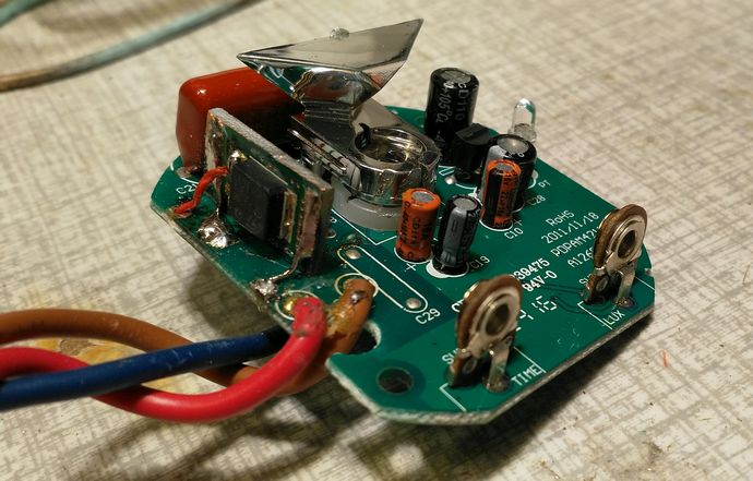
Here the board is mounted again.
You can see the red wire from the 2k2 resistor to the FET gate, the yellow wire that shorts the voltage divider (from the +12V to D2)
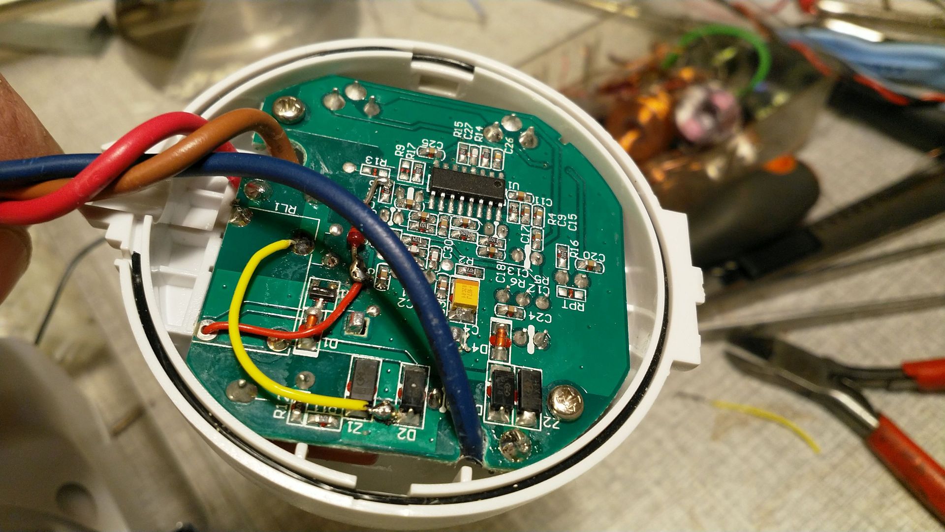
Works fine!
The idle current from the 12V supply is only 4mA, which gives 12V x 4mA = 48mW!
this page is made with n073p4d 2