Homemade low-frequency signal generator for all your hobby needs
A 0.5Hz to 90kHz triangle / sine / square generator with 0 to +-10v, 300mA output.
This signal generator is easy to build and performs really good, even though it is quite simple..
It is based on the legendary XR2206 oscillator chip.
This chip was made by EXAR in the 70's and now discontinued, but is still available from several companies that copied the chip.
Nowadays these copies are quite good (on the internet there are several stories about early non-functional versions), and I have used both the original from 1977 and some from 2023 and 2024.
The generator has 3 frequency ranges:
normal: 50Hz to 9kHz (the mostly used audio range)
high = normal x10: 500Hz to 90kHz (higher audio range up to ultrasound)
low = normal /100: 0.5Hz to 900Hz (lower audio range down to 'blinking signal')
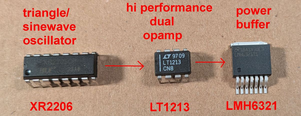
An Opamp chip is added after the oscillator, to get a symmetric squarewave signal and buffered trigger-output, also to amplify the signal to +-10V.
An output buffer is added after that, because we want to be able to drive many different things with it, even a loudspeaker directly.
It is most useful to have a bipolar output (signal going symmetrically around ground). Because we want to go down to a very low frequency, AC coupling is not an option, so the whole circuit is built with DC coupling and a minus and plus supply.
Extra care had to be taken to avoid offset in the signal, but only the sinewave needed an offset adjustment.
The schematics.
See here the final version; the schematic is drawn as 2 pages, which makes it easier to explain how it works.
Part 1 the triangle / sinewave oscillator.
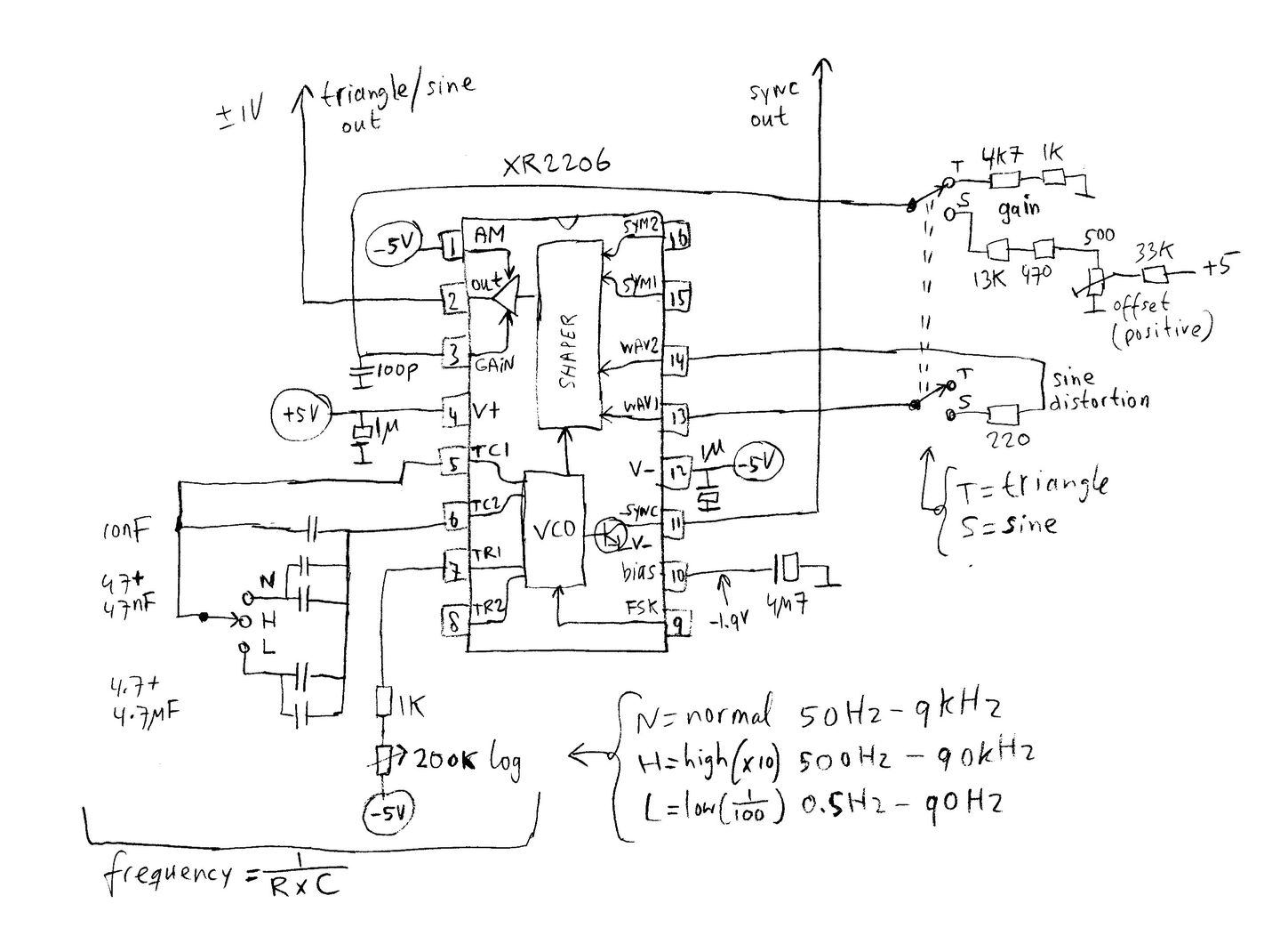
The XR2206 is supplied with +5V and -5V, which gives an output signal that is symmetrical around ground.
Don't use higher voltage, as the "copy versions" of the chip have problems with that.
Decoupling capacitors directly from the supply pins to ground are important for a clean signal, also the bias decoupling at pin 10.
The oscillator generates a triangle using the timing capacitor connected to pins TC1, TC2. It must be high-quality film capacitors for good stability.
The capacitor is charged/discharged by an internal circuit with current sources, which current is defined by the timing resistor connected to pin TR1.
The internal circuit has an output that is available as synchronisation at the "sync" pin 11 with an open-collector transistor.
The frequency can be calculated as Freq [Hz] = 1/(RxC), which means that the frequency gets higher for a smaller resistor, but also that it changes very steep when the resistor gets small. Using a logarithmic potentiometer improves the steep part of the curve and the result is that the frequency changes nicely when you listen to it and turn the potentiometer.
The only issue is that the frequency scale goes from high to low. It would be nicer to use an "anti-logarithmic" potentiometer and connect the potentiometer backwards, but anti-logarithmic potentiometers are hard to get.
The frequency range is switched with a little toggleswitch that has an open mid-position. In the midposition (H), only the 10nF capacitor is connected, and with N or L some bigger capacitors are connected for lower frequency ranges.
The triangle is converted to a sinewave in the Shaper block, where an external resistor defines the amount of shaping.
I started out with a trimpotentiometer, and adjusted the sinewave distortion to approx. -50dB (0.3%) which is fine for nearly all hobby work. Afterwards I found a resistor with the same value as the trimmer, here approx 224 Ohms (a selected 220 Ohms, 10% resistor)
A known issue with the XR2206 is a spike on the top of the sinewave which can give worse distortion, but this is reduced by the 100pF capacitor from pin3 to ground.
The output voltage is adjustable with a resistor from pin3 to ground, and the waveforms have least distortion with a level of approx. +-1V. Since the sinewave level is reduced by the shaper, we need two different gain setting resistors. That is done by using a double switch for the triangle/sine switching. The gains were set with a trimpotentiometer and afterwards by combining two resistors in series for obtaining the same value.
The sinewave has some negative offset, but that is easily adjusted by inserting some positive voltage with the 500 Ohms trimpotentiometer.
Part2 the squarewave limiter, amplifier and output buffer.
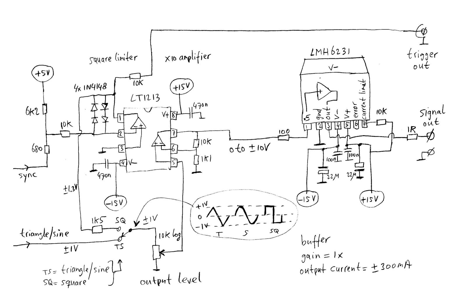
The sync-output from the oscillator is hard to use directly, because it is an open-collector thus low-impedance when pulled to -5V and high-impedance when going to +5V.
To create a symmetric squarewave with low-impedance output, we use an opamp where the feedback path consist of 2 diodes in series for both the positive and negative side. This will result in a nice +-1.3V output, when the input current balance is slightly improved with series resistors of approx 680 Ohms and 6k2 (values not critical), which gives a positive current = +5V/(6k+10k) and a negative current of approx -5V/(680+10k)+5V/6k.
The square ouput is routed to a trigger output via a 10K resistor, so loading of the trigger output doesnt influence the main square signal.
A switch for either square or triangle/sine is connected to a potentiometer for adjusting the output level.
The second half of the opamp chip amplifies the +-1V with 1+(10k/1.1k)= 10 times, so we get a +-10V signal. That is why we use +-15V supply here.
The supply voltages have to be decoupled close to the pins of the chip, as it is very fast and has a lot of gain.
The opamp output can only deliver a few milliamps, so we use a highpower buffer after this.
This chip has built-in current limit and temperature limit. It can get hot, so we mount it on a piece of aluminium plate for cooling.
A 100R resistor at its input and a 1R at the output is needed for unconditional high-frequency stability. Decoupling for both high and low frequencies is important, as the chip is very fast.
Current limit is set to approx 300mA with a 10k resistor, but it can be increased to 400mA when using 15k.
The components.
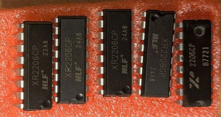
XR2206 was bought on Ebay from satisfyelectronics ($8), LMH6321 and LT1213 from Digikey.
My XR2206 versions can be seen here. The original Exar version is the one most to the right side, with the B7721 marking (means 1977 week 21).
The version used in the actual circuit is a HLF part marked 23A8.
The LT1213 is a dual-opamp with very low offset and high speed.
The LMH6321 is a buffer with a gain of 1, with low offset and high speed.
It comes in a package with exposed backside for cooling. Be careful though, because the back is connected to the negative supply pin, so it must be isolated when mounting the chip on a cooling profile.
The potentiometers are some old high quality parts from my spareparts. I couldn't use the new potmeters that I bought from Digikey, because they were much too lousy. Especially the "frequency" potentiometer needs to be good, and the Digikey part was unstable at the low-resistance end.
The board.
The Schematic is so simple that a board with full groundplane is used and "experimentation-miniboards" are mounted for placing and connecting the chips and components.
The miniboards (homemade) create more room for connecting to the pins of the chips. They are mounted with doublesided tape and also kept in place by the components that are going from a pin to ground.
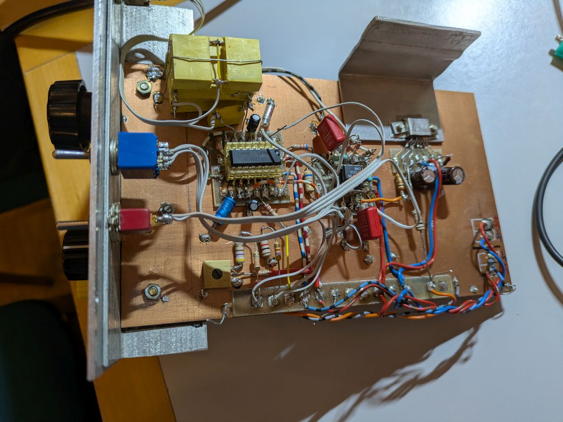
Here is a picture of the board under construction; the oscillator and dual-opamp are operational, but output buffer still missing.
The red and blue wires are + and - 15V, the red/white and blue/white wires are + and - 5V.
The grey (flatcable) wires go to the switches and level-potmeter.
The green/white wires go to the frequency-potmeter.

Here below is the complete circuit.
The buffer is mounted with a little bracket unto a cooling plate, with a silicone-heat-transfer-foil below the chip to isolate its metal back from ground. The pins of the chip have very close spacing, so they are connected to the circuit via some thin wires and a piece of circuitboard.
It can clearly be seen that the board is mounted to the frontplate with an L-shaped piece of metal where the switches go through holes in both the L and the frontplate.
The wires to the two potmeters beneath the board go throught holes in the board.
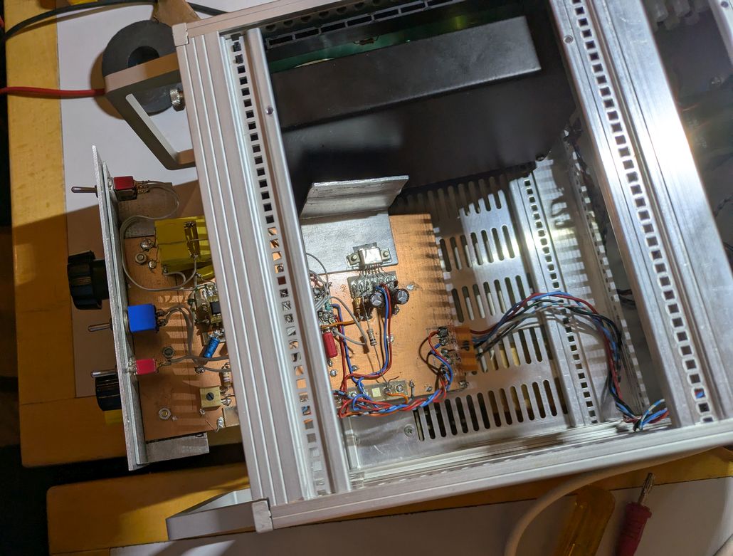
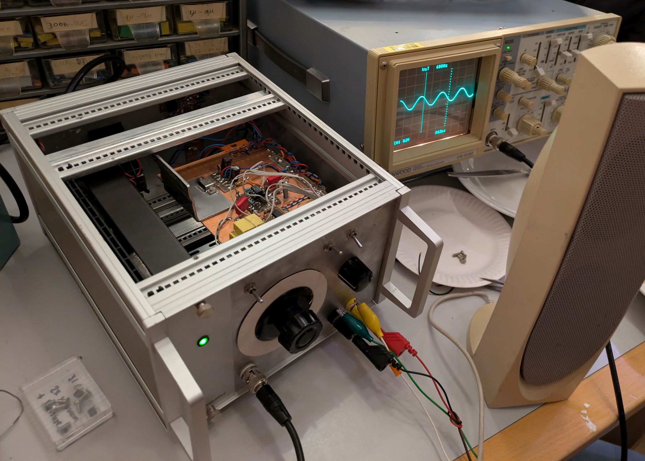
Here the board goes into the cabinet.
The cabinet is reuse of a modular cabinet.
The black module beside the board is the powersupply, which is connected to the board with the orange connector.
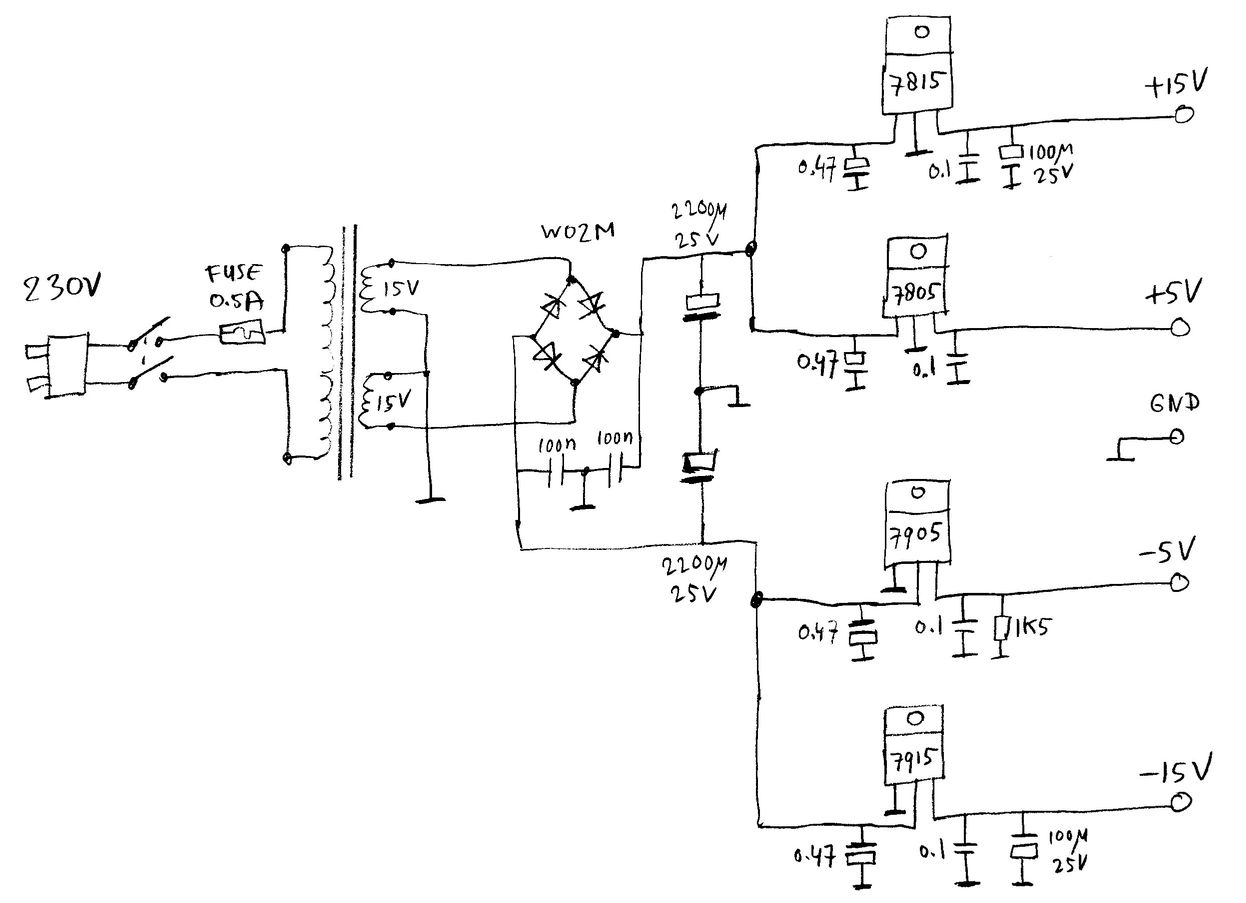
The power supply.
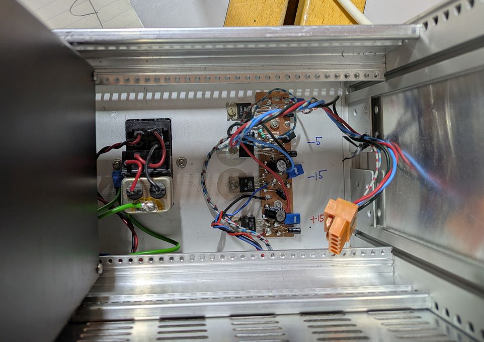
The black powersupply module contains the transformer and rectifiers, whereas the voltage regulators are removed from the module and mounted on the backside of the cabinet for better cooling.
Decoupling capacitors are important for stability, especially for the negative regulators!
The positive regulators are mounted directly on the metal, but the negative regulators have heat-conducting isolation in between because the metal back of those chips are connected to their input.
The mechanical construction.
The functionality of the knobs is most practically layed out like this, so there is enough space to control everything and for output connections:
The scale for the frequency can be marked for "normal" only, because the freq*10 and freq/100 can easily be read from that as well.
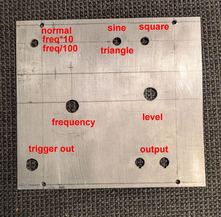
The output has banana-jack connectors, and the trigger output has a BNC connector.
this page is made with Notepad2