Binary counter / Dice
A binary counter that also can be used as a Dice.
This project is a good way to learn about digital circuits..
It is based on the commonly used 74HC193 chip.
This is a binary counter that can count up or down between 0 and 15 (4 bits), and that has a "load" functionality that can reset the output to any value between 0 and 15.
That functionality can be used to make it count between 1 and 6, like a normal dice, but with a binary output (quite nerdy).
The circuit needs a clock signal, which can either come from an external signal generator with variable frequency, or from a little separate circuit with a CD4011 (a standard logic NAND-gate) chip.
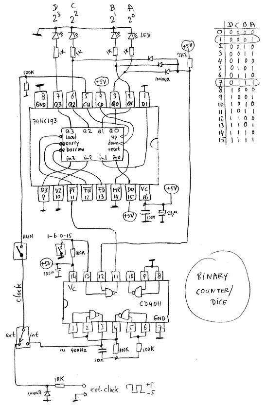
The schematics.

If we look at the circuit without the feedback from the outputs with the 3 1N4148 diodes, it counts from 0 to 15 after which it starts all over at 0.
The binary output can be observed with the 4 LEDs. The bits are normally called D C B A, where A is the " least significant" bit which has a value of 2^0=1, and D is the "most significant" bit which has a value of 2^3=8).
With those 3 diodes connected, the signal at the anodes goes from 'low' to 'high' when the counter output reaches 7 (0111).
One NAND-gate of a CD4011 chip (input pin 12, output pin 11) inverts this to 'low', which triggers the 'load' input of the 74HC193 (This input is 'active-low')
The load inputs (D3 to D0) are strapped to 0001 which means that the counter outputs immediately are preset to 1.
At this output value, the output of the diodes (in fact a simple 3-input AND-gate) is no longer high, which results in a 'load' input signal that is not active anymore and releases the counter to keep on counting.
As the chips are very fast, the time that the output is at 7 is super short, less than 1/10000 of the values 1 through 6.
In that way, you can use the circuit as a dice, by keeping the "run" button pressed for some time and then releasing it, after which the LEDs will show a random binary value 1 to 6.
The feedback loop that loads the counter when 7 is reached, can be disabled by pulling the second input of the NAND-gate (pin 13) to ground, so the output will stay high at any time, and the counter just counts from 0 to 15 instead of 1 to 6.
Digital to Analog conversion.
The binary output from the counter circuit can be converted to an analog voltage that can be measured with a voltmeter or used as a waveform generator.
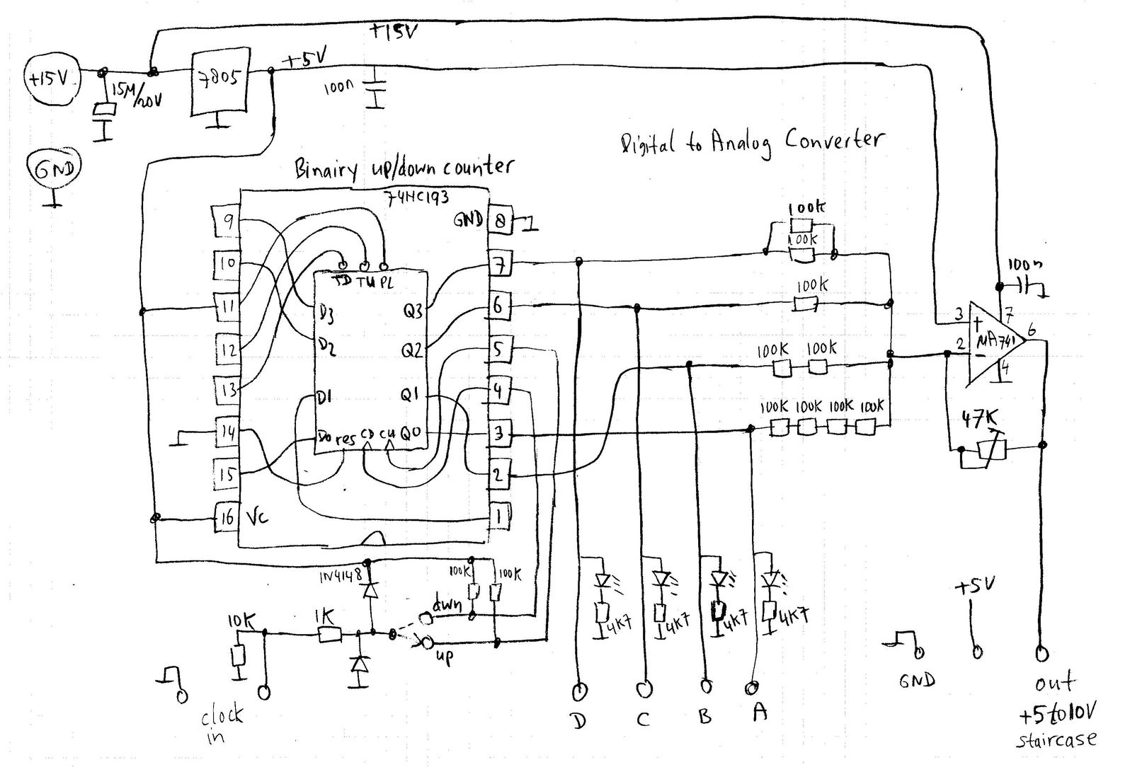
This is done in the following schematic:
Digitally, the binary outputs A to D have a value that gets 2 times bigger from A to B, from B to C etc.
To convert this to analog, we can use resistors to create currents with binary values from the DCBA outputs that switch between 0 and 5V.
A 100kOhm resistor from 5V to Ground will create a current of 5/100k = 5/100mA = 0.05mA.
A resistor of 200kOhm (two 100k resistors in series) will result in a current half that value etc, a resistor of 100kOhms/2 (two 100k resistors in parallel) will result in double the value instead.
When we add all those currents, the combined current will be an analog value that represents the digital DCBA binary value!
In this way, we have created a DAC (Digital to Analog Converter).
When the counter is clocked and counts from 0 to 15, the digital-to-analog conversion of the 4 binary outputs will create a staircase voltage with 16 steps.
After the value of 15, the counter starts from 0 again, thus the staircase will repeat with a frequency of clock/16.
The counting can be reversed by changing the clock input switch setting from "up" to "down", routing the clock to pin4 (CDown) instead of pin5 (CUp).

The easiest way to sum the currents is to use an OPAMP (Operational Amplifier), which is an integrated circuit that can create a "virtual ground" (a point of precise fixed voltage that doesn't consume any current) and thus convert current to voltage very precisely.
Here the legendary uA741 Opamp is used.
This IC needs a + and - supply voltage to be able to make a virtual ground of 0V, but since we only have a positive supply here, we have chosen to use 15V positive supply (it also works with 12V), 0V negative supply, and a virtual ground of 5V (set by the voltage on pin3).
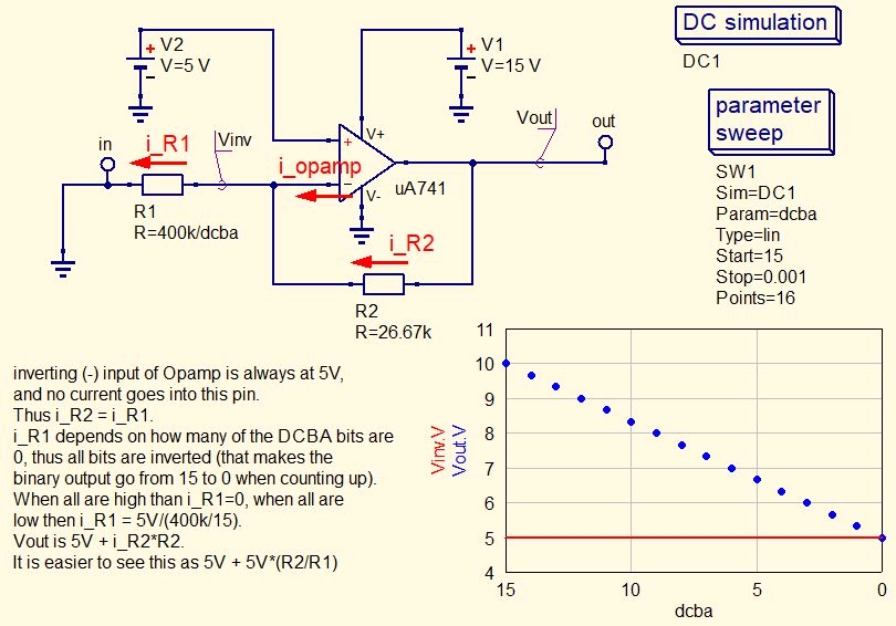
That makes things very confusing, as there now will go no current through the resistors when the binary outputs are at 5V (where there is no voltage over the DAC resistors), and max current will happen when all binary outputs are 0V.
In other words; all bits are inverted (0 is 1, and 1 is 0), and this inverted binary value goes from 15 to 0 when counting up!
Also, when nothing happens on the input, the output will not be 0V but 5V.
When one of the DCBA binary outputs (e.g. bit C) is at 0V, the current through that resistor is (0-5)V/100kOhm = -0.05mA. This current comes from the virtual ground point, pin2 of the Opamp, which is at 5V. Since this is a very high-impedance input of the Opamp and there only is a tiny current flowing through this point, the current will instead flow through the 47kOhm potentiometer. This generates a voltage over that resistor, which is -0.05mA*47kOhm = -2.35V.
That means that the output voltage of the Opamp (pin6) is 2.35V higher than pin2, thus 5+2.35 = 7.35V.
When all binary outputs are at 5V instead, no current flows through the resistors and the Opamp output voltage will be 5V.
When all the binary outputs are 0V, the Opamp output voltage will be highest.
The Opamp can deliver a maximum output voltage of approximately 2V below Vsupply, which here is 15-2=13V. So we have to adjust the potentiometer in order to be sure that the voltage doesnt exceeds this (otherwise our staircase signal will be "clipped" at the top).
Lets say that we want the staircase to go between 5V and 10V:
When all the binary outputs are 0V, the combined current through all DAC resistors is 5V/50kOhm + 5V/100k + 5V/200k + 5V/400k = (8+4+2+1)*5V/400kOhm = 15*0.0125mA = 0.1875mA. So we have to adjust the potmeter to R=V/I = 5V/0.1875mA = 26.67kOhm.
The following simulation shows what happens:

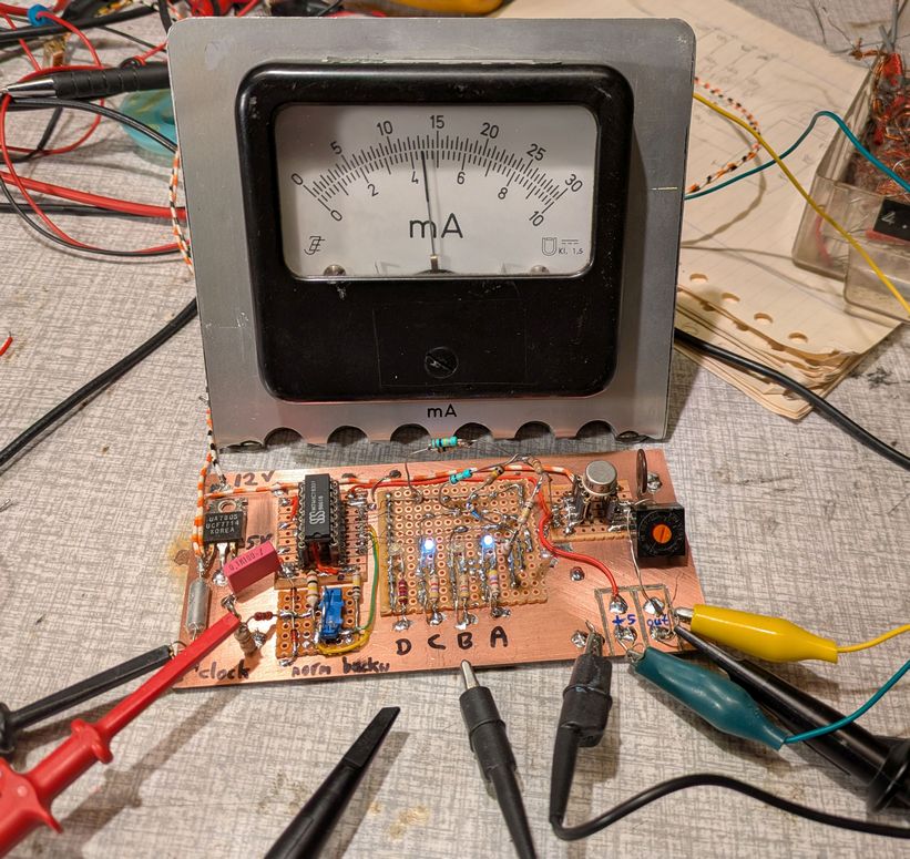
We can connect an analog voltmeter between 5V and the Opamp output, to see the voltage staircase in real time, as in the picture below where a 1mA moving-coil meter with series resistor is connected as analog voltmeter.

to be continued.
this page is made with Notepad2