Homemade powersupply for all your hobby needs
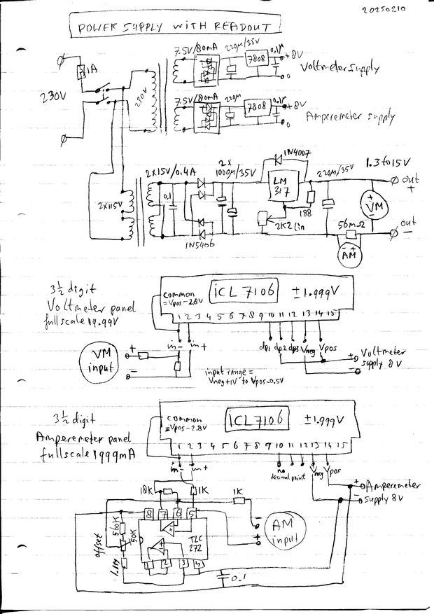
A variable powersupply (1.3 to 15V, 0.8A) with readout.
This powersupply is easy to build and performs really good, even though it is quite simple..
It is based on the universal LM317 chip.
This 'voltage regulator' has built-in short-circuit protection, overheat protection, and has a smart way of making the voltage controllable with an external resistor:
The chip keeps the voltage between output-pin and adjust-pin at 1.25V, while the current of the adjust-pin is only 50uA and doesnt vary much.
Thus when we connect a variable resistor between adjust and ground and configure it so the current through the resistors is much larger than 50uA, we can control the output voltage between minimum 1.25V (when adjust resistor is 0R) and maximum 1.25+1.25*Radj/Rout.
The powersupply has Voltage and Current readout with some surplus voltmeter panels, using the legendary ICL7106 voltmeter chip.
The panels have 3½ digit LCD displays (max reading 1.999) and a built-in stable reference voltage, and the input is from -2V to +2V for a fullscale reading.
It works for a voltage range on the input pins between 1V higher than its negative supply and 1V lower than its positive supply (called 'common-mode' range).
The voltmeter panels came with a tiny isolated 8V supply for both panels, which we re-used as that made it very easy to get the correct common-mode voltage.
The schematics.

For the Voltmeter, a 1/10 resistive voltage division is added to scale the voltage (0 to 19.99V).
For the Amperemeter, an Opamp chip is added for the current readout (0 to 1999mA), to amplify the tiny voltage over a current-sense resistor.
This opamp circuit uses the "common" voltage of the ICL7106 as ground, in order to level-shift the measured voltage. It is a high-performance chip with inputs that work down to 0V, and with low offset. The remaining offset can be adjusted to 0 by injecting a little current into pin6 together with the input current from the voltage over the measurement resistor.
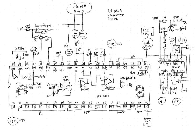
The schematics of the meters.
Both meter panels contain the icl7106 DVM (Digital Volt Meter) chip with a icl8069 voltage reference, a CD4030 EXOR chip (this is identical to a CD4070) to control the decimal points, and a 2SC1815 transistor to detect 'low battery' when the supply voltage gets below 6V.

The icl7106 chip is a complete system with built-in auto-zero circuit, and the voltage measurement works like this:
The integrator capacitor is charged with a current that is dependent on the input voltage. The result is a linear slope and an output voltage that goes negative, relative to Vcommon (Pin32).
After 100ms the integrator input is switched to the Ref voltage (here 1.0V). The integrator output voltage (Pin27) now goes back to Vcommon with a positive going linear slope, and the time this took is a direct measure of the measured voltage.
NB In the above schematic inside the icl7106, the switches for the integration sequence (and also of the AutoZero circuit) are not drawn for simplicity.
For a default configuration as above, with 1V reference, Rint=470k, Cint=220nF, a +1.9V input voltage results in a ramp amplitude of -1.9V.
The chip includes also the circuitry to control the LCD display. Pin21 drives the BackPlane of the LCD with a 50Hz squarewave. The display segments are switched on/off when the segment outputs are inverted/not-inverted compared to the backplane.

to be continued.
this page is made with Notepad2