How to modify a TAPO C310 security cam for use of PoE (Power over Ethernet)
How to make a simple modification to a security cam, so it can be powered via the LAN cable.
The TAPO C310 can be easily modified to a simple PoE scheme using the powersupply that was delivered with your cam, exploiting "spare pairs" in the LAN cable.
Here is my experience with the modification:
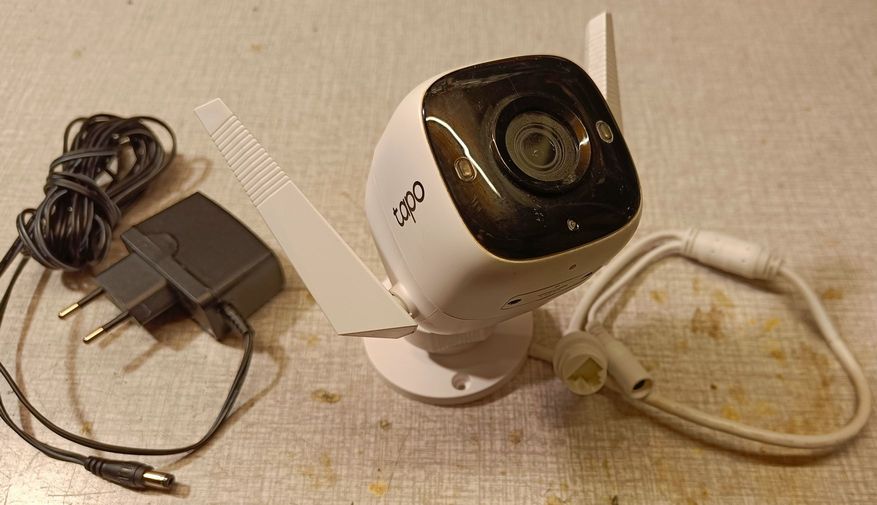
TP-Link Tapo C310, and also Tapo C320ws.
A modern camera with night-vision.
It comes with a 9V powersupply that normally is connected via a standard 5.5mm connector.
It can be easily modified for a simple PoE with the existing 9V powersupply.
NO change inside the cam is needed!
This is the camera described below on this page.
A LAN cable has 8 wires (4 pairs), but normally only 4 wires (2pairs) are used for data.
So the unused 4 wires can be used to inject Powersupply voltage in the LAN cable on the far end and to connect those wires as supply on the camera end, instead of using a separate supply cable..
The short cable coming out of the camera has only 6 wires and they don't have standard LAN colours;
When the camera is opened, it can be seen that these wires are as follows:
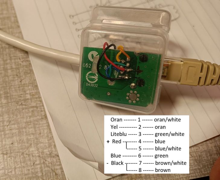
2 LAN pairs: green&blue, yellow&orange
Powersupply: red, black
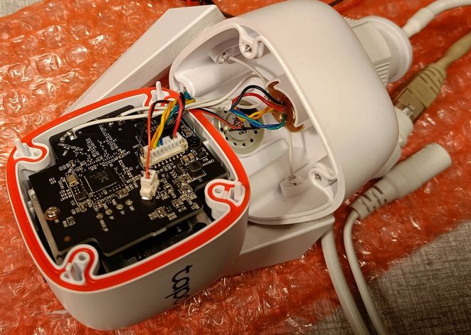
I had the idea that there would be all 8 LAN wires from the LAN connector to the 'cablejoint' halfway the short cable,
but when the cablejoint was removed, it turned out that only 4 wires go to the LAN connector:
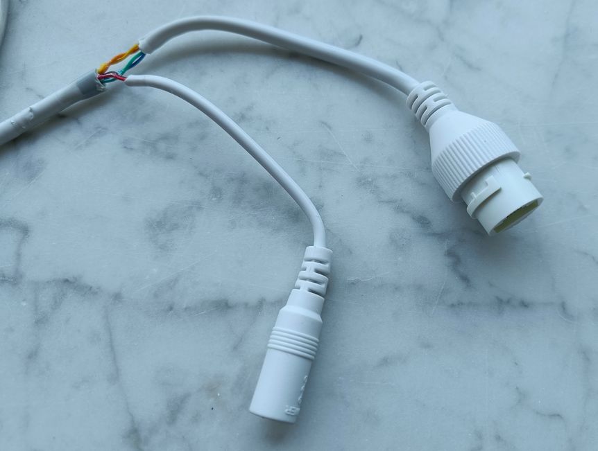
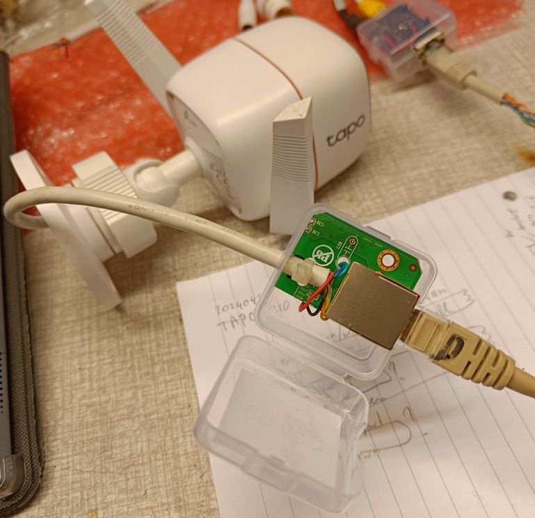
So there was no other possibility than cutting off the end of the cable and soldering the 6 wires to a LAN connector.
Finding a LAN connector where the data and supply voltage can be soldered to, can be easily done by sawing a corner off an old PC LAN card.
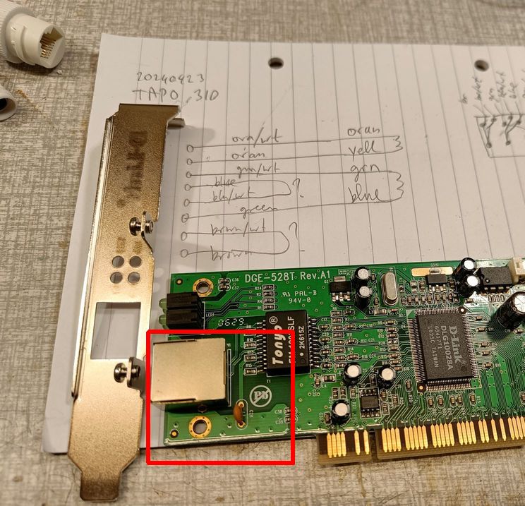
The camera cable is soldered to the connector and secured with a strap.
And it fits in a tiny plastic box:
Alternative for the modification:
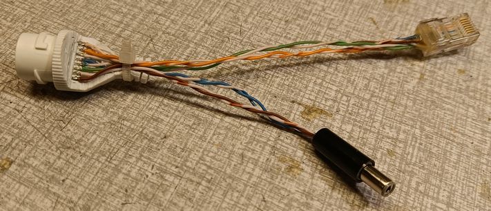
If you don't want to modifiy the camera's cable, it is also possible to keep the camera cable as it is with the LAN and DC plugs, and make a short "adapter cable" instead. This will interface to the LAN cable that has PoE.
For example a removed cam cable can be used like this (cut away part of the LAN connector so the solderpins get exposed):
PoE injector:
On the far end (PC), a similar connection can inject the powersupply into the LAN cable.
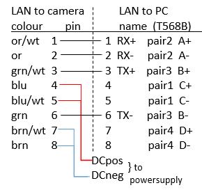
Here 2 LAN cables have to be connected together (a long cable going to the camera and a shorter cable going to the PC), with 2 of the pairs going to the powersupply instead of to the PC.
I had two 10-pin LAN connectors (outer 2 pins not used) with metal shielding, that easily could be soldered together.
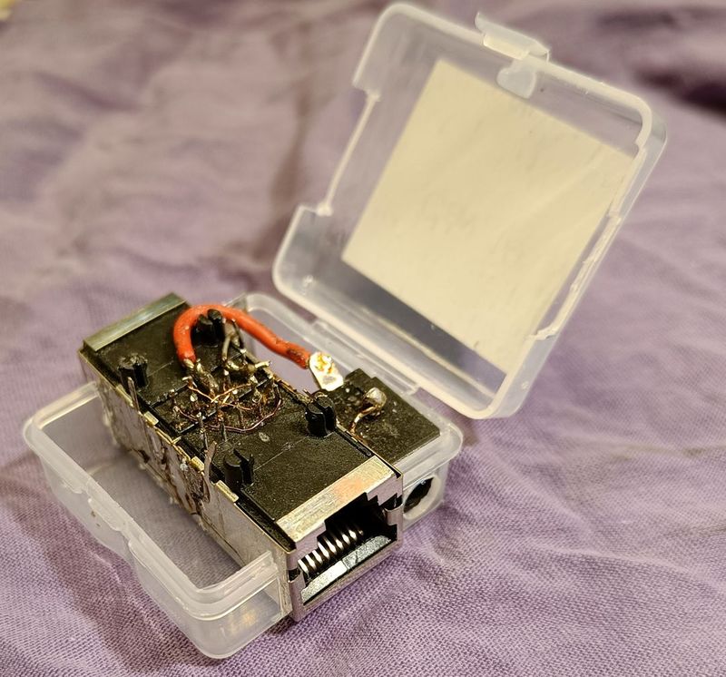
A powersupply plug was also soldered to it, and everything fitted in a tiny plastic box, making a nice PoE injector.
Pin1 must be connected to pin1 etc, but pins 4,5 and 7,8 coming from the cable to the cam go to the powersupply.
The connections look like this, when the left side is the LAN cable to the cam, right side is LAN cable to PC:
The inside of the "PoE injector":
Now we can connect the 9V powersupply at the PC end of the cable, and can place the camera far away and only connected with a LAN cable.
I tested that the camera works with a supply voltage down to 5.5V on the 9V input, so we don't have to be afraid of too much voltage drop on the cable.
The camera uses 220mA during day and 350mA at night (when the IR light is on), so we can tolerate a cable resistance of 3.5V/(350 * 9/5.5)mA = 5.5 Ohms which means that it will work over at least 60 meters of standard cat5e LAN cable.

| camera cable | pin | LAN cable | pin | signal |
| orange | 1 | orange/white | 1 | RX+ |
| yellow | 2 | orange | 2 | RX- |
| lightblue | 3 | green/white | 3 | TX+ |
| red | 4+5 | blue | 4+5 | Vpos |
| 5+4 | blue/white | 5+4 | ||
| blue | 6 | green | 6 | TX- |
| black | 7+8 | brown/white | 7+8 | Vneg |
| 8+7 | brown | 8+7 |
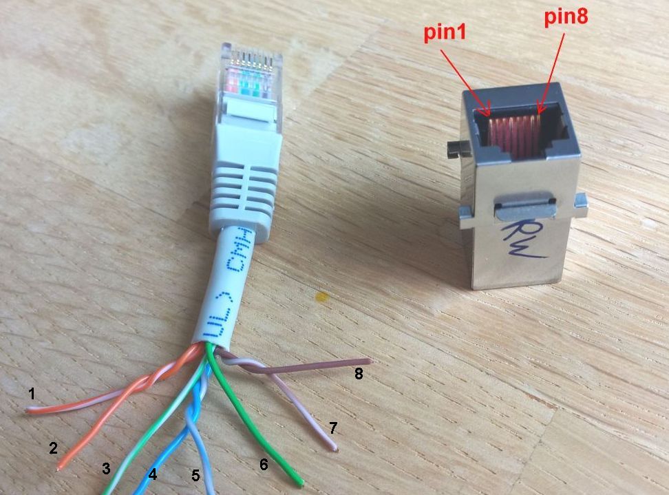
This shows the pin numbering and colour followingorder of a LAN cable:
That's it!.
this page is made with Notepad2