timer with decimal counter
Measuring speed of toy-cars on a race track.
This project is a good way to learn about digital circuits and displays..
It uses standard logic chips and doesn't need any software.
The counter:
The timer uses a 74HC192, which is is a BCD (Binary Coded Decimals) counter that can count up or down between 0 and 9 (4 bits), and that has a "load" functionality that can reset the output to a predetermined value.
It has inputs and outputs that can be interconnected so several chips can be used together for counting longer times.
Using BCD counters means that every chip represents one decimal (between 0 and 9) of a bigger number, exactly as we write decimal numbers.
The output of each chip can then be decoded and shown on a display.
The following schematic is a 3½ digit BCD counter. It can be used to count from 0000 to 1999.
The Terminal Count Up output of the 74HC192 clocks the next.
More 74HC192 can be added in the same way, in order to get more digits.
The last 74HC192 clocks a flipflop (there are 2 flipflops in a 4013), in order to get 1 extra bit (Most Significant Bit) which is called a half digit (even though it really is just a quarter).
The reset input can be used to reset the output to 0000 before starting the counter clock.

The 74HC192 has the following pins:
MR Master Reset: When this pin is 1, it resets all outputs to 0.
PL Parallel Load: When 0, it loads the D inputs into the Q outputs.
CP_U Clock Pulse Up: on a transition from 0 to 1, the counter counts 1 up.
CP_D Clock Pulse Down: on a transition from 0 to 1, the counter counts 1 down.
TC_U Terminal Count Up: when counting up and reaching 10, this output clocks the next counter 1 up.
TC_D Terminal Count Down: when counting down and reaching less than 0, this output clocks the next counter 1 down.
NB:
Reset overrides all load and count inputs.
When counting up or down, the unclocked clock input must be 1.
An example of a 74HC192 counter sequence, using all inputs:
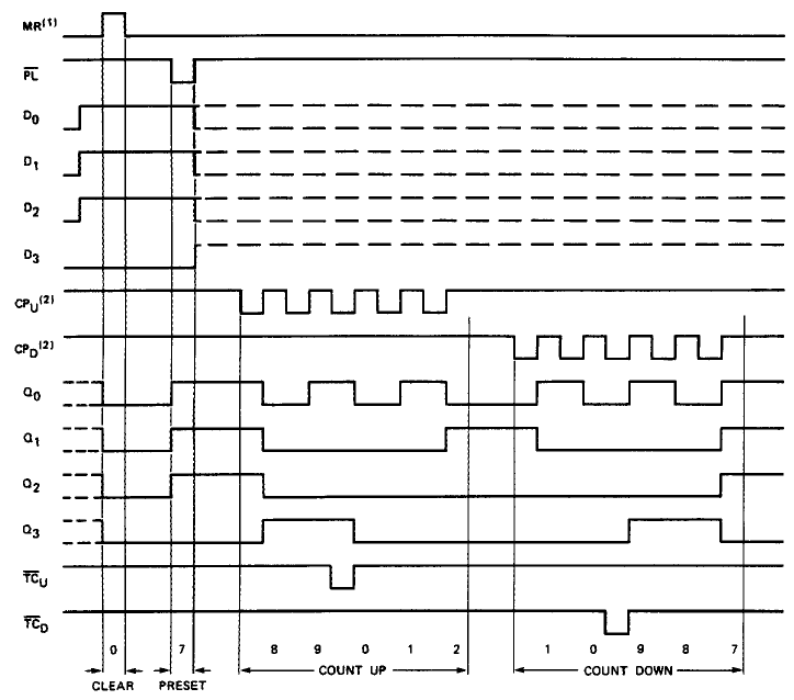
In the above sequence, the following happens:
Clear (MR resets the outputs to 0).
Preset (Loads to 7).
Count UP to 8 -> 9 -> 0 & Terminal Count Up -> 1 -> 2
Count DOWN to 1 -> 0 -> 9 & Terminal Count down -> 8 -> 7
The clock:
The clock for the timer has to be quite accurate and stable over temperature.
Also the following has to be considered: the counter of the timer is clocked by the positive flank of the clock, and when starting the timer (by releasing the Master Reset of the counters), there can be a delay anywhere between 0 and 1 clock cycle before the first flank happens. If we use a 1msec clock and we cannot live with a 1msec latency, we might want to add some extra counter between clock circuit and counter, and also control that with the same Reset. By adding a divide-by-4, we will only have 0.25msec latency which is much better.
The wellknown LM555 is a great chip for a clock oscillator (and for learning how stuff works) :
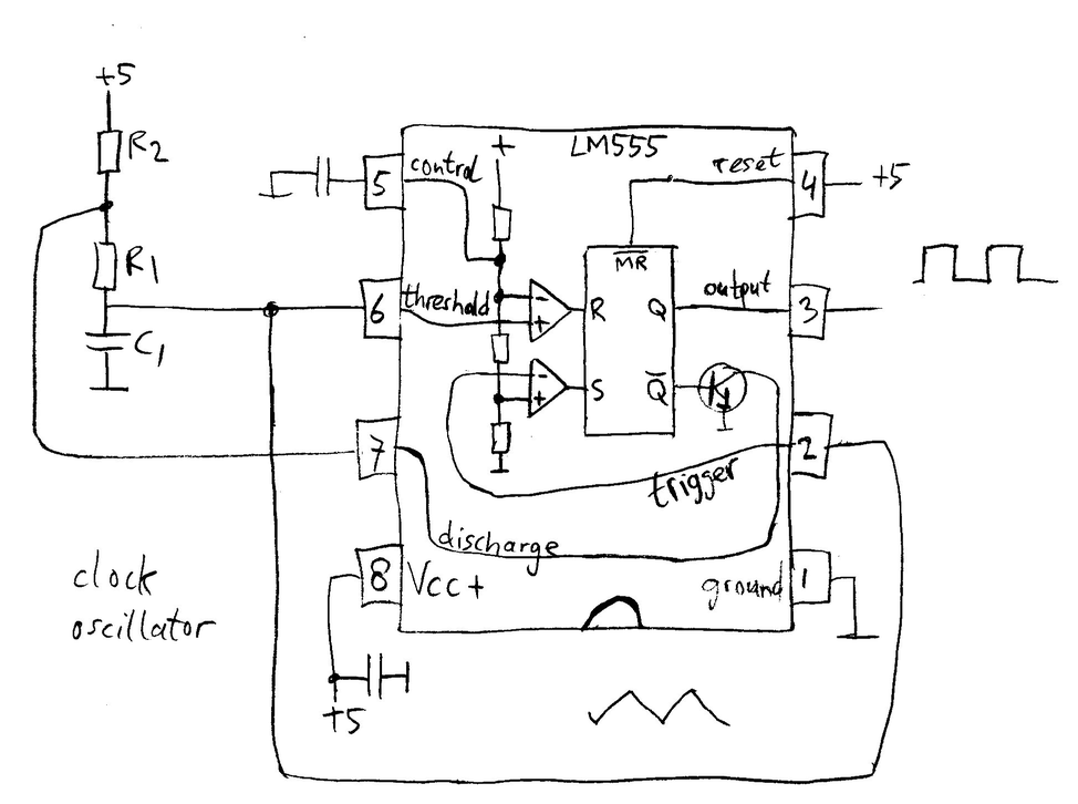
to be continued......
Displaying the time results:
We can either use LED displays or LCD displays.
LED displays look nicer, but can be hard to read in sunlight, so an LCD is used. This also uses much less current, but is a bit more difficult to drive because you need a symmetric clock for the backplane.
A 40-pin 4½ digit LCD display is used. Digit 5 is just a ½ digit, which means it can only be 0 or 1.
The pin nrs and segment explanation, are as seen from front:
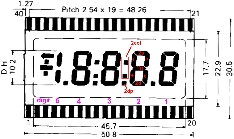
Fortunately the pinout is almost standard for all brands of LCD displays, but the pins can be named slightly differently.
A 40-pin 3½ digit display could also be used; there the connections are the same but all 4th digit segments are n.c.
Pin numbers are as seen from the backside (which is easiest when you want to measure some of the signals)
| pin nr | segment | pin nr | segment |
| 40 | backplane (com) | 1 | backplane (com) |
| 39 | sign vertical (|) | 2 | sign horizontal (-) |
| 38 | low battery | 3 | 5bc half digit (K) |
| 37 | 4g | 4 | 4 digital point (DP) |
| 36 | 4f | 5 | 4e | 35 | 4a | 6 | 4d |
| 34 | 4b | 7 | 4c |
| 33 | 3 colon (L) | 8 | 3 digital point (DP) |
| 32 | 3g | 9 | 3e |
| 31 | 3f | 10 | 3d |
| 30 | 3a | 11 | 3c |
| 29 | 3b | 12 | 2 digital point (DP) |
| 28 | 2 colon (L) | 13 | 2e |
| 27 | 2g | 14 | 2d |
| 26 | 2f | 15 | 2c |
| 25 | 2a | 16 | 1 digital point (DP) |
| 24 | 2b | 17 | 1e |
| 23 | 1g | 18 | 1d |
| 22 | 1f | 19 | 1c |
| 21 | 1a | 20 | 1b |
The display driver:
Here we use the MC14543, 1 chip for each digit of the display.
The Latch Disable pin has to be 1 because it is only used for freezing the number, and the Blank pin has to be 0 otherwise all segments will go OFF.
The Phase pin must be connecte to the LCD display Backplane squarewave clock. When a segment is switched ON, its output is a squarewave with a phase opposite to the LCD backplane, when OFF it has the same phase as the backplane.
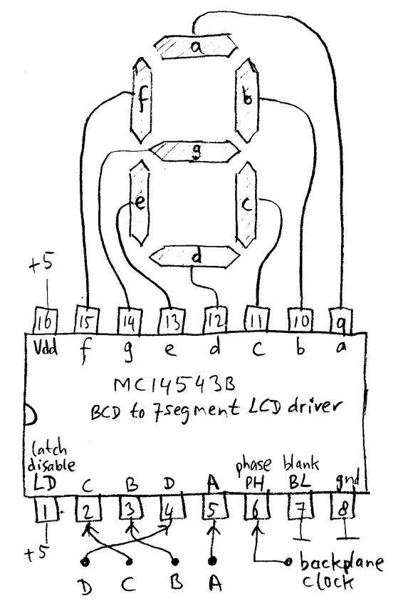
The backplane clock is also driving the LCD Display Backplane, which is quite a high load and thus needs a buffer.
Another important thing is that the clock needs to be perfect 50% on/off, otherwise the display will be destroyed after some time. So normally a flipflop is used to divide by 2 (this flips between 0 and 1 for every input clock positive flank, and thus creates a perfect square).
The display and driver of a surplus circuit were used.
This board had the following circuit for the backplane clock (the non-connected parts in the schematic below are used for other functions on this surplus board):
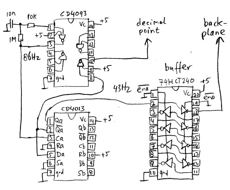
The CD4093 forms the oscillator, the CD4013 is the flipflop where Q is the divided output. The inverted_Q output can be used to be connected to e.g. digital points and colons that have to be ON and thus must be in a phase that is opposite to the backplane.
to be continued...to be continued...to be continued...to be continued
this page is made with Notepad2