This is a description of what is inside the phantastic Logitech Z4, complete with detailed schematics.
Also, it describes a project to make another control unit that has more inputs and switching possibilities.. .
And if you bought the subwoofer alone, as often is the case from a recycling shop, here you can learn how to build your own control box and what small speakers are compatible.. .
The Logitech Z4 comes in two versions; the Z4 and the Z4i.
The difference is the amplifier chip that is used, but from the outside and performance-wise they are totally identical.
Z4: amplifier chip is STMicroelectronics STA540.
Z4i: amplifier chip is STMicroelectronics TDA7377.
It has a really good sound and is totally analog (no switchmode stuff, thus no radio disturbance and no cheap chinese powersupply), and is cheap to buy as second hand.
It consists of a control pod with preamp and controls, the subwoofer with built-in amplifier and powersupply, and two small speakers.
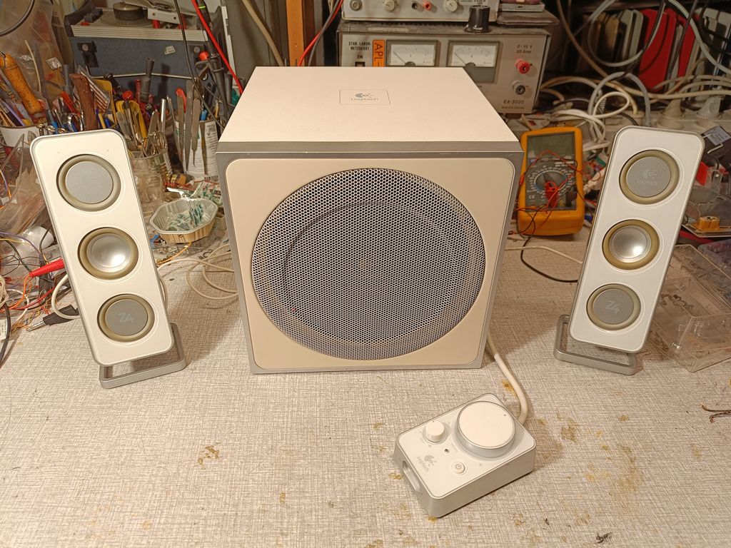
My Z4 is black, my Z4i is white. This is how it looked before the modifications. The controlpod only has a cable to the subwoofer and two jack connectors on the front, for line input and headset output:
We wanted to modify it and add the following functionality:
- switchable audio inputs from two PCs, controlled by usb from those PCs.
- automatic standby when both PCs are off.
- headset and mic connected to the control pod, audio switchable between headset and speaker.
We reverse-engineered it totally in order to understand it and to be able to modify it.
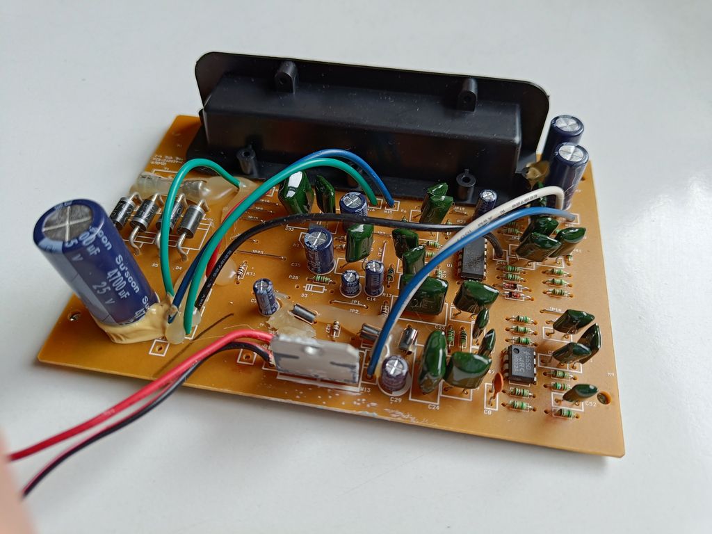
The circuit board inside the subwoofer box can be removed from the back:
As the schematics were no nowhere to be found on the internet, we had to draw it ourselves.
This was quite straightforward, by using the technique that is described here: how to make schematics
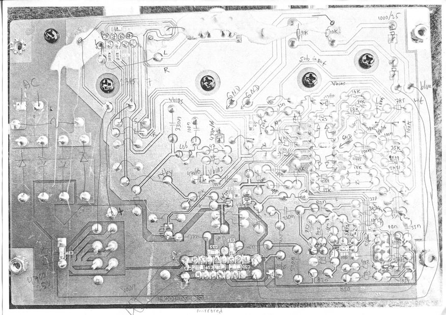
The layout inclusive components as seen here below is made by mirroring a picture of the bottom of the circuit board and drawing the components as seen from the top.
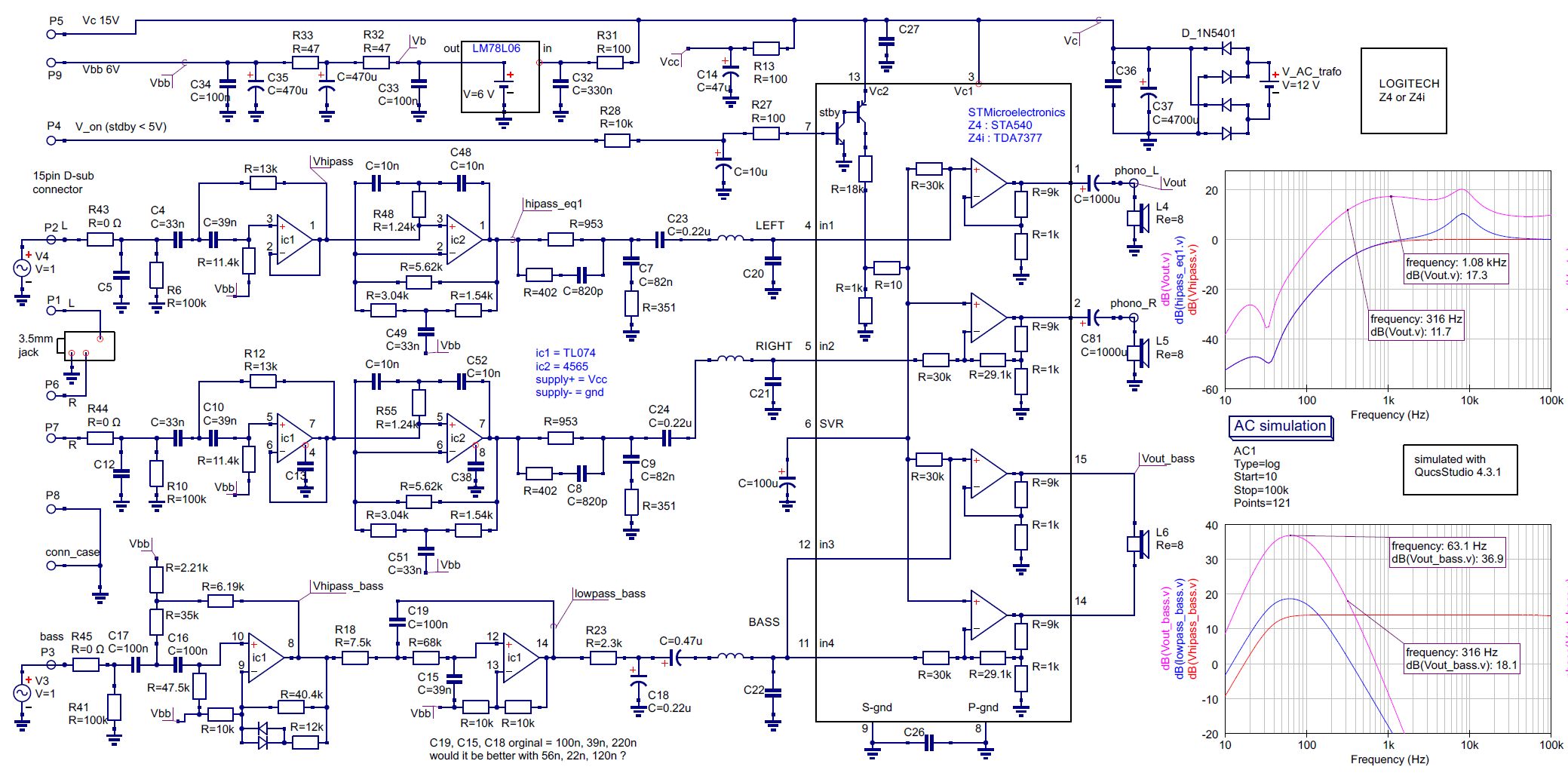
The schematic is drawn in QucsStudio, and also simulated to see how it behaves over frequency.
The circuitry inside the subwoofer looks originally like this:
(On the right side is the gain vs frequency for the small speakers and below that for the subwoofer output)
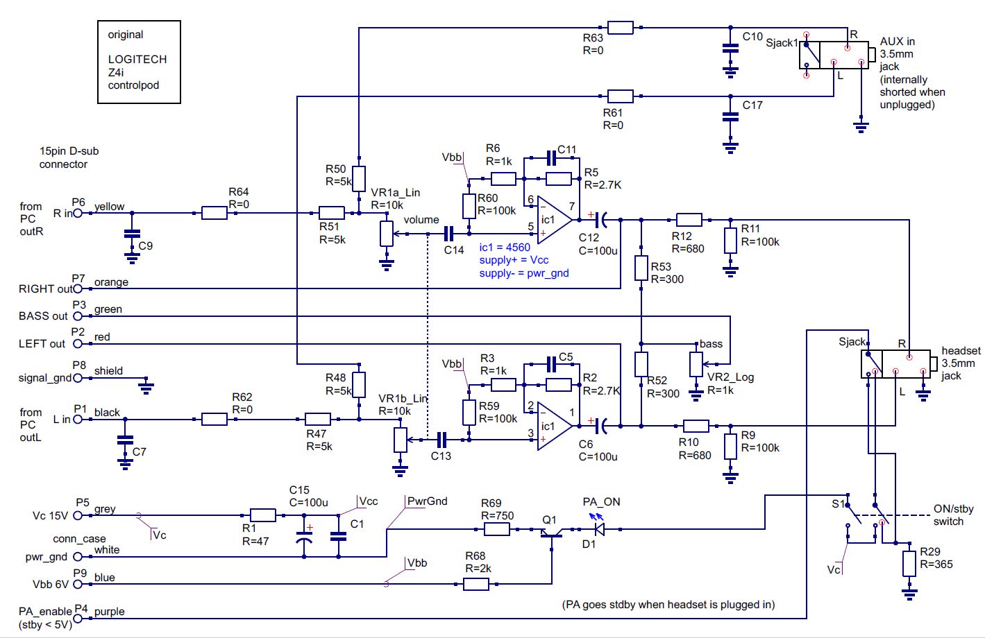
The schematics of the controlpod as it was originally, looks like this:
PAGE UNDER CONSTRUCTION
this page is made with n073p4d 2