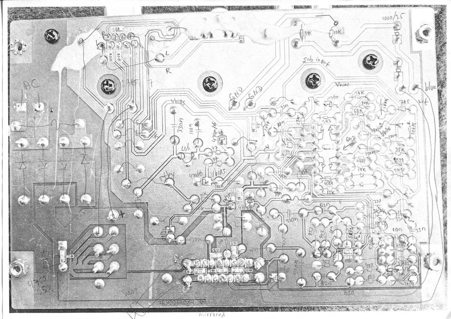
The following technique has worked fine for me in many projects, but it is VERY important to take the needed time to do the groundwork. .
When the printed circuit board is double sided or even single sided, it can be done! Multilayer boards are more problematic, as there will be invisible traces inside the board.
The following technique has worked fine for me in many projects, but it is VERY important to take the needed time to do the groundwork.
Step1:
Take a very good quality picture of both the bottom and the top of the board (or just only the bottom). It takes a lot of experimentation with the light and camera, because everything has to be sharp and with equal lighting over the whole picture and there must be no shades or bright spots. If the board is too big to get it right over the whole surface, then you have to split it up in several pictures.
Step2:
Use a photo editing software to improve the pictures, so the traces and the connections between all solderpoints are all nicely visible. If there is any doubt, check with the real board and edit the picture, so it is totally clear what is connected to what.
If you are a bit sloppy here, it will haunt you later when you look at the finished schematics and notice that it turned out to be something "not possible that this can ever work".
Step3:
Use the photo editing to mirror the picture of the bottom of the board, so it is like looking from the top. Increase the opacity, so it will be easier to see components that you will draw on top of it later.
Print it on paper.
It must be in such big scale that drawing components on top of it will not obscure important details and traces. If you only have an A4 size printer, you might want to divide the picture in multiple prints.
Now you can lay the real board (topside up) beside the printed picture(s), and start drawing the components on the correct places and the values. If you can read the reference numbers of the components, it is also a big help to write those (that needs a lot of space, so again important that your printed picture is big enough).
Step4:
Now it will be easy to draw the schematic, while constantly checking if it makes sense and you didnt overlook any connections.
For an example, click this picture to see the page about the Logitech Z4:
